- AAL:
-
See: authenticator assurance level.
- ABAC:
-
See: attribute-based access control.
- access control:
-
The process of granting or denying specific requests for obtaining and using information and related information processing services.
- ACDC
-
See: Authentic Chained Data Container.
- action
-
Something that is actually done (a ‘unit of work’ that is executed) by a single actor (on behalf of a given party), as a single operation, in a specific context.Source: eSSIF-Lab.
- actor
-
An entity that can act (do things/execute actions), e.g. people, machines, but not organizations. A digital agent can serve as an actor acting on behalf of its principal.Source: eSSIF-Lab.
- address
-
See: network address.
- administering authority:
-
See: administering body.
- administering body:
-
A legal entity delegated by a governing body to administer the operation of a governance framework and governed infrastructure for a digital trust ecosystem, such as one or more trust registries.
- agency:
-
In the context of decentralized digital trust infrastructure, the empowering of a party to act independently of its own accord, and in particular to empower the party to employ an agent to act on the party’s behalf.
- agent:
-
An actor that is executing an action on behalf of a party (called the principal of that actor). In the context of decentralized digital trust infrastructure, the term “agent” is most frequently used to mean a digital agent.
- AID:
-
See autonomic identifier.
- anonymous
-
An adjective describing when the identity of a natural person or other actor is unknown.
- anycast:
-
Anycast is a network addressing and routing methodology in which a single IP-address is shared by devices (generally servers) in multiple locations. Routers direct packets addressed to this destination to the location nearest the sender, using their normal decision-making algorithms, typically the lowest number of BGP network hops. Anycast routing is widely used by content delivery networks such as web and name servers, to bring their content closer to end users.
- anycast address:
-
A network address (especially an IP address) used for anycast routing of network transmissions.
- appraisability (of a communications endpoint):
-
The ability for a communication endpoint identified with a verifiable identifier to be appraised for the set of its properties that enable a relying party or a verifier to make a trust decision about communicating with that endpoint.
- assurance level
-
A level of confidence that may be relied on by others. Different types of assurance levels are defined for different types of trust assurance mechanisms. Examples include authenticator assurance level, federation assurance level, and identity assurance level.
- appropriate friction:
-
A user-experience design principle for information systems (such as digital wallets) specifying that the level of attention required of the holder for a particular transaction should provide a reasonable opportunity for an informed choice by the holder.
- attestation:
-
The issue of a statement, based on a decision, that fulfillment of specified requirements has been demonstrated. In the context of decentralized digital trust infrastructure, an attestation usually has a digital signature so that it is cryptographically verifiable.
- attribute:
-
An identifiable set of data that describes an entity, which is the subject of the attribute.
- attribute-based access control:
-
An access control approach in which access is mediated based on attributes associated with subjects (requesters) and the objects to be accessed. Each object and subject has a set of associated attributes, such as location, time of creation, access rights, etc. Access to an object is authorized or denied depending upon whether the required (e.g., policy-defined) correlation can be made between the attributes of that object and of the requesting subject.
- audit (of system controls):
-
Independent review and examination of records and activities to assess the adequacy of system controls, to ensure compliance with established policies and operational procedures.
- audit log:
-
An audit log is a security-relevant chronological record, set of records, and/or destination and source of records that provide documentary evidence of the sequence of activities that have affected at any time a specific operation, procedure, event, or device.
- auditor (of an entity):
-
The party responsible for performing an audit. Typically an auditor must be accredited.
- authentication(of a user; process; or device):
-
Verifying the identity of a user, process, or device, often as a prerequisite to allowing access to resources in an information system.
- authentication(of a user; process; or device):
-
Verifying the identity of a user, process, or device, often as a prerequisite to allowing access to resources in an information system.
- authenticator
-
Something the claimant possesses and controls (typically a cryptographic module or password) that is used to authenticate the claimant’s identity.
- authenticator assurance level
-
A measure of the strength of an authentication mechanism and, therefore, the confidence in it.
- authenticator assurance level
-
A measure of the strength of an authentication mechanism and, therefore, the confidence in it.
- Authentic Chained Data Container:
-
A digital data structure designed for both cryptographic verification and chaining of data containers. ACDC may be used for digital credentials.
- authenticity:
-
The property of being genuine and being able to be verified and trusted; confidence in the validity of a transmission, a message, or message originator.
- authorization
-
The process of verifying that a requested action or service is approved for a specific entity.
- authorized organizational representative
-
A person who has the authority to make claims, sign documents or otherwise commit resources on behalf of an organization.
- authorization graph:
-
A graph of the authorization relationships between different entities in a trust-community. In a digital trust ecosystem, the governing body is typically the trust root of an authorization graph. In some cases, an authorization graph can be traversed by making queries to one or more trust registries.
- authoritative source:
-
A source of information that a relying party considers to be authoritative for that information. In ToIP architecture, the trust registry authorized by the governance framework (#governance-framework) for a [trust community is typically considered an authoritative source by the members of that trust community. A system of record is an authoritative source for the data records it holds. A trust root is an authoritative source for the beginning of a trust chain.
- authority:
-
A party of which certain decisions, ideas, rules etc. are followed by other parties.
- autonomic identifier:
-
The specific type of self-certifying identifier specified by the KERI specifications.
- biometric:
-
A measurable physical characteristic or personal behavioral trait used to recognize the AID, or verify the claimed identity, of an applicant. Facial images, fingerprints, and iris scan samples are all examples of biometrics.
- blockchain:
-
A distributed digital ledger of cryptographically-signed transactions that are grouped into blocks. Each block is cryptographically linked to the previous one (making it tamper evident) after validation and undergoing a consensus decision. As new blocks are added, older blocks become more difficult to modify (creating tamper resistance). New blocks are replicated across copies of the ledger within the network, and any conflicts are resolved automatically using established rules.
- broadcast:
-
In computer networking, telecommunication and information theory, broadcasting is a method of transferring a message to all recipients simultaneously. Broadcast delivers a message to all nodes in the network using a one-to-all association; a single datagram (or packet) from one sender is routed to all of the possibly multiple endpoints associated with the broadcast address. The network automatically replicates datagrams as needed to reach all the recipients within the scope of the broadcast, which is generally an entire network subnet.
- broadcast address:
-
A broadcast address is a network address used to transmit to all devices connected to a multiple-access communications network. A message sent to a broadcast address may be received by all network-attached hosts. In contrast, a multicast address is used to address a specific group of devices, and a unicast address is used to address a single device. For network layer communications, a broadcast address may be a specific IP address.
- C2PA:
-
See: Coalition for Content Provenance and Authenticity.
- CA:
-
See: certificate authority.
- CAI:
-
See: Content Authenticity Initiative.
- certification authority:
-
See: certificate authority.
- certificate authority:
-
The entity in a public key infrastructure (PKI) that is responsible for issuing public key certificates and exacting compliance to a PKI policy.
- certification (of a party):
-
A comprehensive assessment of the management, operational, and technical security controls in an information system, made in support of security accreditation, to determine the extent to which the controls are implemented correctly, operating as intended, and producing the desired outcome with respect to meeting the security requirements for the system.
- certification body:
-
A legal entity that performs certification.
- chain of trust:
-
See: trust chain.
- chained credentials:
-
Two or more credentials linked together to create a trust chain between the credentials that is cryptographically verifiable.
- chaining:
-
See: trust chain.
- channel:
-
See: communication channel.
- ciphertext:
-
Encrypted (enciphered) data. The confidential form of the plaintext that is the output of the encryption function.
- claim:
-
An assertion about a subject, typically expressed as an attribute or property of the subject. It is called a “claim” because the assertion is always made by some party, called the issuer of the claim, and the validity of the claim must be judged by the verifier.
- Coalition for Content Provenance and Authenticity:
-
C2PA is a Joint Development Foundation project of the Linux Foundation that addresses the prevalence of misleading information online through the development of technical standards for certifying the source and history (or provenance) of media content.
- communication:
-
The transmission of information.
- communication endpoint:
-
A type of communication network node. It is an interface exposed by a communicating party or by a communication channel. An example of the latter type of a communication endpoint is a publish-subscribe topic or a group in group communication systems.
- communication channel:
-
A communication channel refers either to a physical transmission medium such as a wire, or to a logical connection over a multiplexed medium such as a radio channel in telecommunications and computer networking. A channel is used for information transfer of, for example, a digital bit stream, from one or several senders to one or several receivers.
- communication metadata:
-
Metadata that describes the sender, receiver, routing, handling, or contents of a communication. Communication metadata is often observable even if the contents of the communication are encrypted.
- communication session:
-
A finite period for which a communication channel is instantiated and maintained, during which certain properties of that channel, such as authentication of the participants, are in effect. A session has a beginning, called the session initiation, and an ending, called the session termination.
- complex password:
-
A password that meets certain security requirements, such as minimum length, inclusion of different character types, non-repetition of characters, and so on.
- compliance:
-
In the context of decentralized digital trust infrastructure, the extent to which a system, actor, or party conforms to the requirements of a governance framework or trust framework that pertains to that particular entity.
- concept:
-
An abstract idea that enables the classification of entities, i.e., a mental construct that enables an instance of a class of entities to be distinguished from entities that are not an instance of that class. A concept can be identified with a term.
- confidential computing:
-
Hardware-enabled features that isolate and process encrypted data in memory so that the data is at less risk of exposure and compromise from concurrent workloads or the underlying system and platform.
- confidentiality:
-
In a communications context, a type of privacy protection in which messages use encryption or other privacy-preserving technologies so that only authorized parties have access.
- connection:
-
A communication channel established between two communication endpoints. A connection may be ephemeral or persistent.
- Content Authenticity Initiative:
-
The Content Authenticity Initiative (CAI) is an association founded in November 2019 by Adobe, the New York Times and Twitter. The CAI promotes an industry standard for provenance metadata defined by the C2PA. The CAI cites curbing disinformation as one motivation for its activities.
- controller (of a key:
-
In the context of digital communications, the entity in control of sending and receiving digital communications. In the context of decentralized digital trust infrastructure, the entity in control of the cryptographic keys necessary to perform cryptographically verifiable actions using a digital agent and digital wallet. In a ToIP context, the entity in control of a ToIP endpoint.
- consent management:
-
A system, process or set of policies under which a person agrees to share personal data for specific usages. A consent management system will typically create a record of such consent.
- controlled document:
-
A governance document whose authority is derived from a primary document.
- correlation privacy:
-
In a communications context, a type of privacy protection in which messages use encryption, hashes, or other privacy-preserving technologies to avoid the use of identifiers or other content that unauthorized parties may use to correlate the sender and/or receiver(s).
- counterparty:
-
From the perspective of one party, the other party in a transaction, such as a financial transaction.
- credential:
-
A container of claims describing one or more subjects. A credential is generated by the issuer of the credential and given to the holder of the credential. A credential typically includes a signature or some other means of proving its authenticity. A credential may be either a physical credential or a digital credential.
- credential family:
-
A set of related digital credentials defined by a governing body (typically in a governance framework) to empower transitive trust decisions among the participants in a digital trust ecosystem.
- credential governance framework:
-
A governance framework for a credential family. A credential governance framework may be included within or referenced by an ecosystem governance framework.
- credential offer:
-
A protocol request invoked by an issuer to offer to issue a digital credential to the holder of a digital wallet. If the request is invoked by the holder, it is called an issuance request.
- credential request:
-
See: issuance request.
- credential schema:
-
A data schema describing the structure of a digital credential. The W3C Verifiable Credentials Data Model Specification defines a set of requirements for credential schemas.
- criterion:
-
In the context of terminology, a written description of a concept that anyone can evaluate to determine whether or not an entity is an instance or example of that concept. Evaluation leads to a yes/no result.
- cryptographic binding:
-
Associating two or more related elements of information using cryptographic techniques.
- cryptographic key:
-
A key in cryptography is a piece of information, usually a string of numbers or letters that are stored in a file, which, when processed through a cryptographic algorithm, can encode or decode cryptographic data. Symmetric cryptography refers to the practice of the same key being used for both encryption and decryption. Asymmetric cryptography has separate keys for encrypting and decrypting. These keys are known as the public keys and private keys, respectively.
- cryptographic trust:
-
A specialized type of technical trust that is achieved using cryptographic algorithms.
- cryptographic verifiability:
-
The property of being cryptographically verifiable.
- cryptographically verifiable:
-
A property of a data structure that has been digitally signed using a private key such that the digital signature can be verified using the public key. Verifiable data, verifiable messages, verifiable credentials, and verifiable data registries are all cryptographically verifiable. Cryptographic verifiability is a primary goal of the ToIP Technology Stack.
- cryptographically bound:
-
A state in which two or more elements of information have a cryptographic binding.
- custodial wallet:
-
A digital wallet that is directly in the custody of a principal, i.e., under the principal’s direct personal or organizational control. A digital wallet that is in the custody of a third party is called a non-custodial wallet.
- custodian:
-
A third party that has been assigned rights and duties in a custodianship arrangement for the purpose of hosting and safeguarding a principal’s private keys, digital wallet and digital assets on the principal’s behalf. Depending on the custodianship arrangement, the custodian may act as an exchange and provide additional services, such as staking, lending, account recovery, or security features.
- custodianship arrangement:
-
The informal terms or formal legal agreement under which a custodian agrees to provide service to a principal.
- dark pattern:
-
A design pattern, mainly in user interfaces, that has the effect of deceiving individuals into making choices that are advantageous to the designer.
- data:
-
In the pursuit of knowledge, data is a collection of discrete values that convey information, describing quantity, quality, fact, statistics, other basic units of meaning, or simply sequences of symbols that may be further interpreted. A datum is an individual value in a collection of data.
- datagram:
-
See: data packet.
- data packet:
-
In telecommunications and computer networking, a network packet is a formatted unit of data carried by a packet-switched network such as the Internet. A packet consists of control information and user data; the latter is also known as the payload. Control information provides data for delivering the payload (e.g., source and destination network addresses, error detection codes, or sequencing information). Typically, control information is found in packet headers and trailers.
- data schema:
-
A description of the structure of a digital document or object, typically expressed in a machine-readable language in terms of constraints on the structure and content of documents or objects of that type. A credential schema is a particular type of data schema.
- data subject:
-
The natural person that is described by personal data. Data subject is the term used by the EU General Data Protection Regulation.
- data vault:
-
See: digital vault.
- decentralized identifier:
-
A globally unique persistent identifier that does not require a centralized registration authority and is often generated and/or registered cryptographically. The generic format of a DID is defined in section 3.1 DID Syntax of the W3C Decentralized Identifiers (DIDs) 1.0 specification. A specific DID scheme is defined in a DID method specification.
- decentralized identity:
-
A digital identity architecture in which a digital identity is established via the control of a set of cryptographic keys in a digital wallet so that the controller is not dependent on any external identity provider or other third party.
- Decentralized Identity Foundation:
-
A non-profit project of the Linux Foundation chartered to develop the foundational components of an open, standards-based, decentralized identity ecosystem for people, organizations, apps, and devices.
- Decentralized Web Node:
-
A decentralized personal and application data storage and message relay node, as defined in the DIF Decentralized Web Node specification. Users may have multiple nodes that replicate their data between them.
- deceptive pattern:
-
See: dark pattern.
- decryption:
-
The process of changing ciphertext into plaintext using a cryptographic algorithm and key. The opposite of encryption.
- deep link:
-
In the context of the World Wide Web, deep linking is the use of a hyperlink that links to a specific, generally searchable or indexed, piece of web content on a website (e.g. “https://example.com/path/page”), rather than the website’s home page (e.g., “https://example.com”). The URL contains all the information needed to point to a particular item. Deep linking is different from mobile deep linking, which refers to directly linking to in-app content using a non-HTTP URI.
- definition:
-
A textual statement defining the meaning of a term by specifying criterion that enable the concept identified by the term to be distinguished from all other concepts within the intended scope.
- delegation:
-
TODO
- delegation credential:
-
TODO
- dependent:
-
An entity for the caring for and/or protecting/guarding/defending of which a guardianship arrangement has been established with a guardian.
- device controller:
-
The controller of a device capable of digital communications, e.g., a smartphone, tablet, laptop, IoT device, etc.
- dictionary:
-
A dictionary is a listing of lexemes (words or terms) from the lexicon of one or more specific languages, often arranged alphabetically, which may include information on definitions, usage, etymologies, pronunciations, translation, etc. It is a lexicographical reference that shows inter-relationships among the data. Unlike a glossary, a dictionary may provide multiple definitions of a term depending on its scope or context.
- DID controller:
-
An entity that has the capability to make changes to a DID document. A DID might have more than one DID controller. The DID controller(s) can be denoted by the optional controller property at the top level of the DID document. Note that a DID controller might be the DID subject.
- DID document:
-
A set of data describing the DID subject, including mechanisms, such as cryptographic public keys, that the DID subject or a DID delegate can use to authenticate itself and prove its association with the DID. A DID document might have one or more different representations as defined in section 6 of the W3C Decentralized Identifiers (DIDs) 1.0 specification.
- DID method:
-
A definition of how a specific DID method scheme is implemented. A DID method is defined by a DID method specification, which specifies the precise operations by which DIDs and DID documents are created, resolved, updated, and deactivated.
- DID subject:
-
The entity identified by a DID and described by a DID document. Anything can be a DID subject: person, group, organization, physical thing, digital thing, logical thing, etc.
- DID URL:
-
A DID plus any additional syntactic component that conforms to the definition in section 3.2 of the W3C Decentralized Identifiers (DIDs) 1.0 specification. This includes an optional DID path (with its leading / character), optional DID query (with its leading ? character), and optional DID fragment (with its leading # character).
- digital agent:
-
In the context of decentralized digital trust infrastructure, an agent (specifically a type of software agent) that operates in conjunction with a digital wallet.
- digital asset:
-
A digital asset is anything that exists only in digital form and comes with a distinct usage right. Data that do not possess that right are not considered assets.
- digital certificate:
-
See: public key certificate.
- digital credential:
-
A credential in digital form that is signed with a digital signature and held in a digital wallet. A digital credential is issued to a holder by an issuer; a proof of the credential is presented by the holder to a verifier.
- digital ecosystem:
-
A digital ecosystem is a distributed, adaptive, open socio-technical system with properties of self-organization, scalability and sustainability inspired from natural ecosystems. Digital ecosystem models are informed by knowledge of natural ecosystems, especially for aspects related to competition and collaboration among diverse entities.
- digital identity:
-
An identity expressed in a digital form for the purpose representing the identified entity within a computer system or digital network.
- digital rights management:
-
Digital rights management (DRM) is the management of legal access to digital content. Various tools or technological protection measures (TPM) like access control technologies, can restrict the use of proprietary hardware and copyrighted works. DRM technologies govern the use, modification and distribution of copyrighted works (e.g. software, multimedia content) and of systems that enforce these policies within devices.
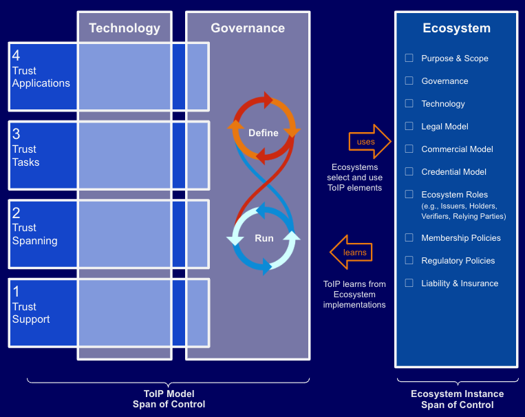
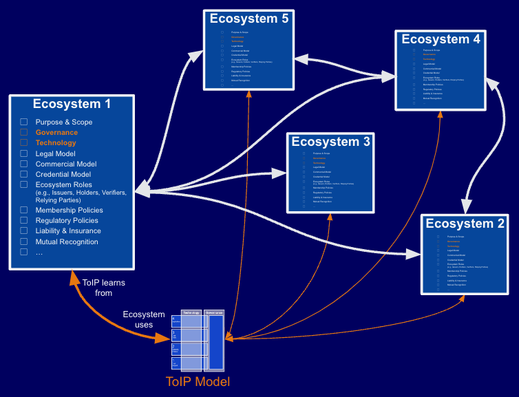
- digital trust ecosystem:
-
A digital ecosystem in which the participants are one or more interoperating trust communities. Governance of the various roles of governed parties within a digital trust ecosystem (e.g., issuers, holders, verifiers, certification bodies, auditors) is typically managed by a governing body using a governance framework as recommended in the ToIP Governance Stack. Many digital trust ecosystems will also maintain one or more trust lists and/or trust registries.
- digital trust utility:
-
An information system, network, distributed database, or blockchain designed to provide one or more supporting services to higher level components of decentralized digital trust infrastructure. In the ToIP stack, digital trust utilities are at Layer 1. A verifiable data registry is one type of digital trust utility.
- digital signature:
-
A digital signature is a mathematical scheme for verifying the authenticity of digital messages or documents. A valid digital signature, where the prerequisites are satisfied, gives a recipient very high confidence that the message was created by a known sender (authenticity), and that the message was not altered in transit (integrity).
- digital vault:
-
A secure container for data whose controller is the principal. A digital vault is most commonly used in conjunction with a digital wallet and a digital agent. A digital vault may be implemented on a local device or in the cloud; multiple digital vaults may be used by the same principal across different devices and/or the cloud; if so they may use some type of synchronization. If the capability is supported, data may flow into or out of the digital vault automatically based on subscriptions approved by the controller.
- digital wallet:
-
A user agent, optionally including a hardware component, capable of securely storing and processing cryptographic keys, digital credentials, digital assets and other sensitive private data that enables the controller to perform cryptographically verifiable operations. A non-custodial wallet is directly in the custody of a principal. A custodial wallet is in the custody of a third party. Personal wallets are held by individual persons; enterprise wallets are held by organizations or other legal entities.
- distributed ledger:
-
A distributed ledger (also called a shared ledger or distributed ledger technology or DLT) is the consensus of replicated, shared, and synchronized digital data that is geographically spread (distributed) across many sites, countries, or institutions. In contrast to a centralized database, a distributed ledger does not require a central administrator, and consequently does not have a single (central) point-of-failure. In general, a distributed ledger requires a peer-to-peer (P2P) computer network and consensus algorithms so that the ledger is reliably replicated across distributed computer nodes (servers, clients, etc.). The most common form of distributed ledger technology is the blockchain, which can either be on a public or private network.
- domain:
-
See: security domain.
- DRM:
-
See: digital rights management.
- DWN:
-
See: Decentralized Web Node.
- ecosystem:
-
See: digital ecosystem.
- ecosystem governance framework:
-
A governance framework for a digital trust ecosystem. An ecosystem governance framework may incorporate, aggregate, or reference other types of governance frameworks such as a credential governance framework or a utility governance framework.
- ecosystem governance framework:
-
A governance framework for a digital trust ecosystem. An ecosystem governance framework may incorporate, aggregate, or reference other types of governance frameworks such as a credential governance framework or a utility governance framework.
- eIDAS:
-
eIDAS (electronic IDentification, Authentication and trust Services) is an EU regulation with the stated purpose of governing “electronic identification and trust services for electronic transactions”. It passed in 2014 and its provisions came into effect between 2016-2018.
- encrypted data vault:
-
See: digital vault.
- encryption:
-
Cryptographic transformation of data (called plaintext) into a form (called ciphertext) that conceals the data’s original meaning to prevent it from being known or used. If the transformation is reversible, the corresponding reversal process is called decryption, which is a transformation that restores encrypted data to its original state.
- end-to-end encryption:
-
Encryption that is applied to a communication before it is transmitted from the sender’s communication endpoint and cannot be decrypted until after it is received at the receiver’s communication endpoint. When end-to-end encryption is used, the communication cannot be decrypted in transit no matter how many intermediaries are involved in the routing process.
- End-to-End Principle:
-
The end-to-end principle is a design framework in computer networking. In networks designed according to this principle, guaranteeing certain application-specific features, such as reliability and security, requires that they reside in the communicating end nodes of the network. Intermediary nodes, such as gateways and routers, that exist to establish the network, may implement these to improve efficiency but cannot guarantee end-to-end correctness.
- endpoint:
-
See: communication endpoint.
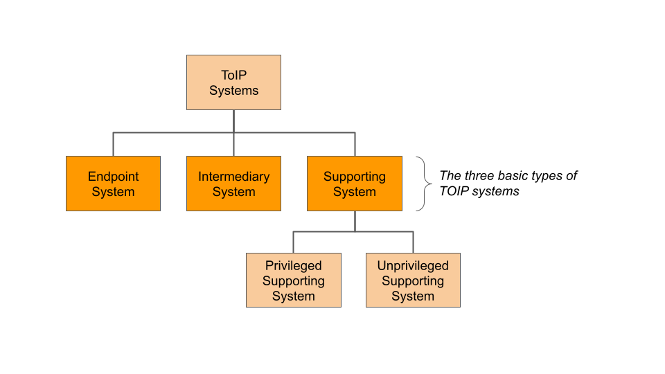
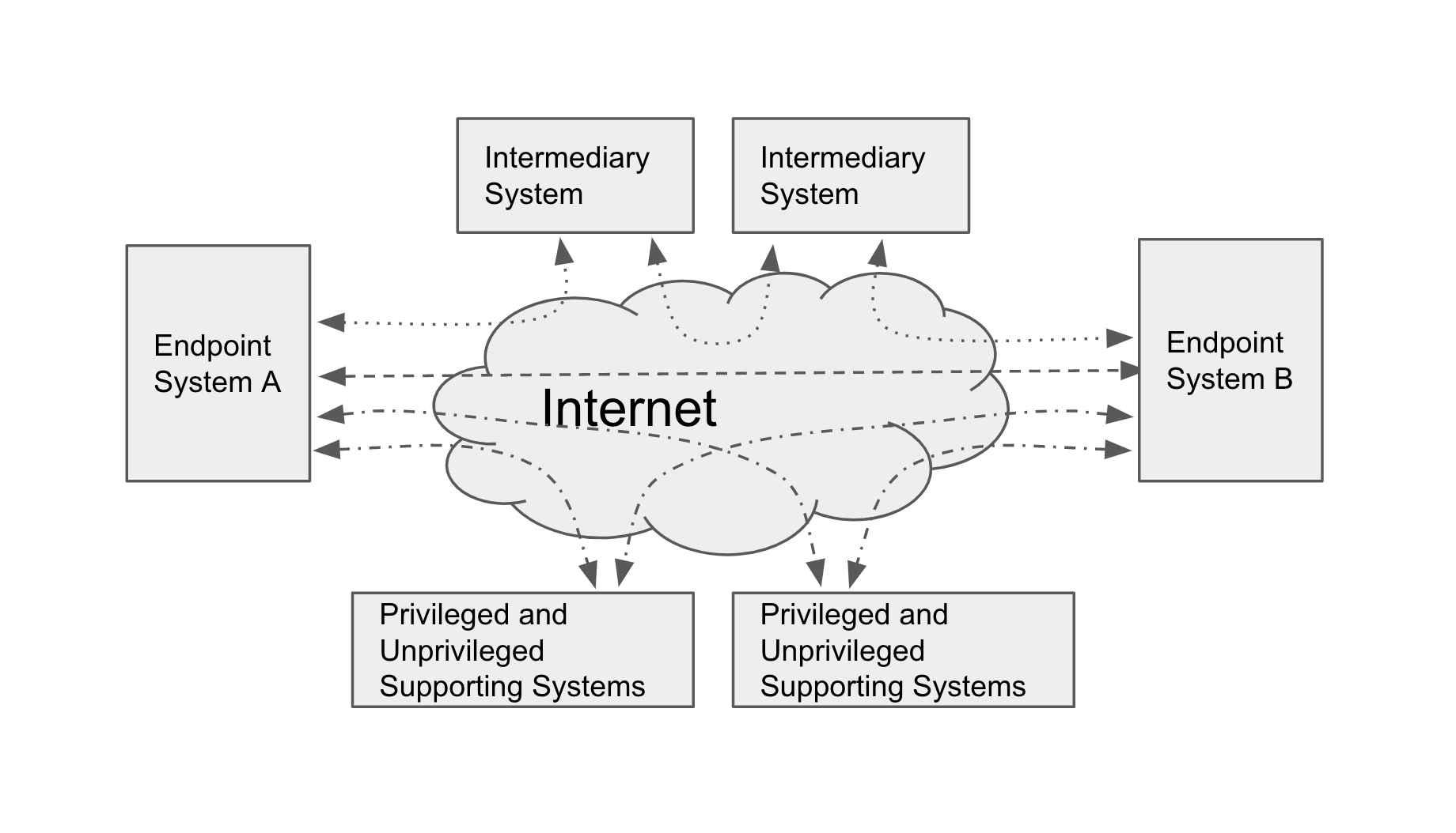
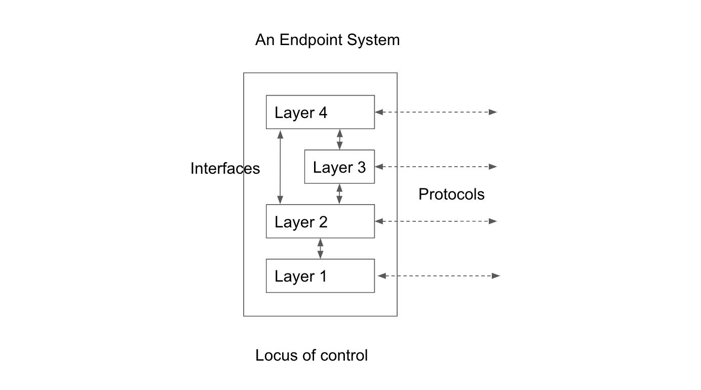
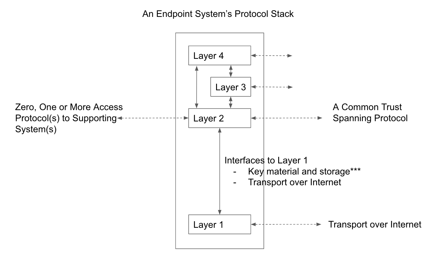
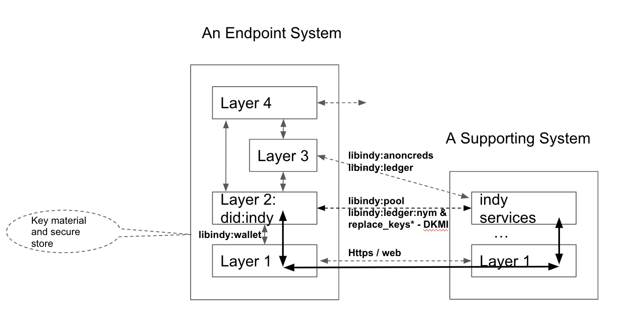
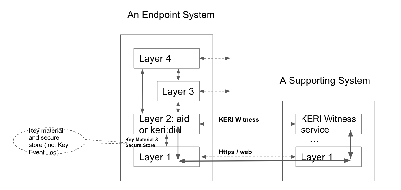
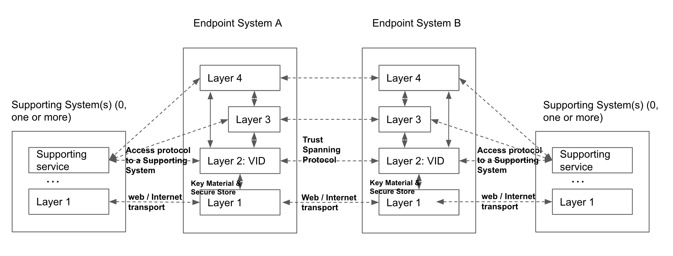
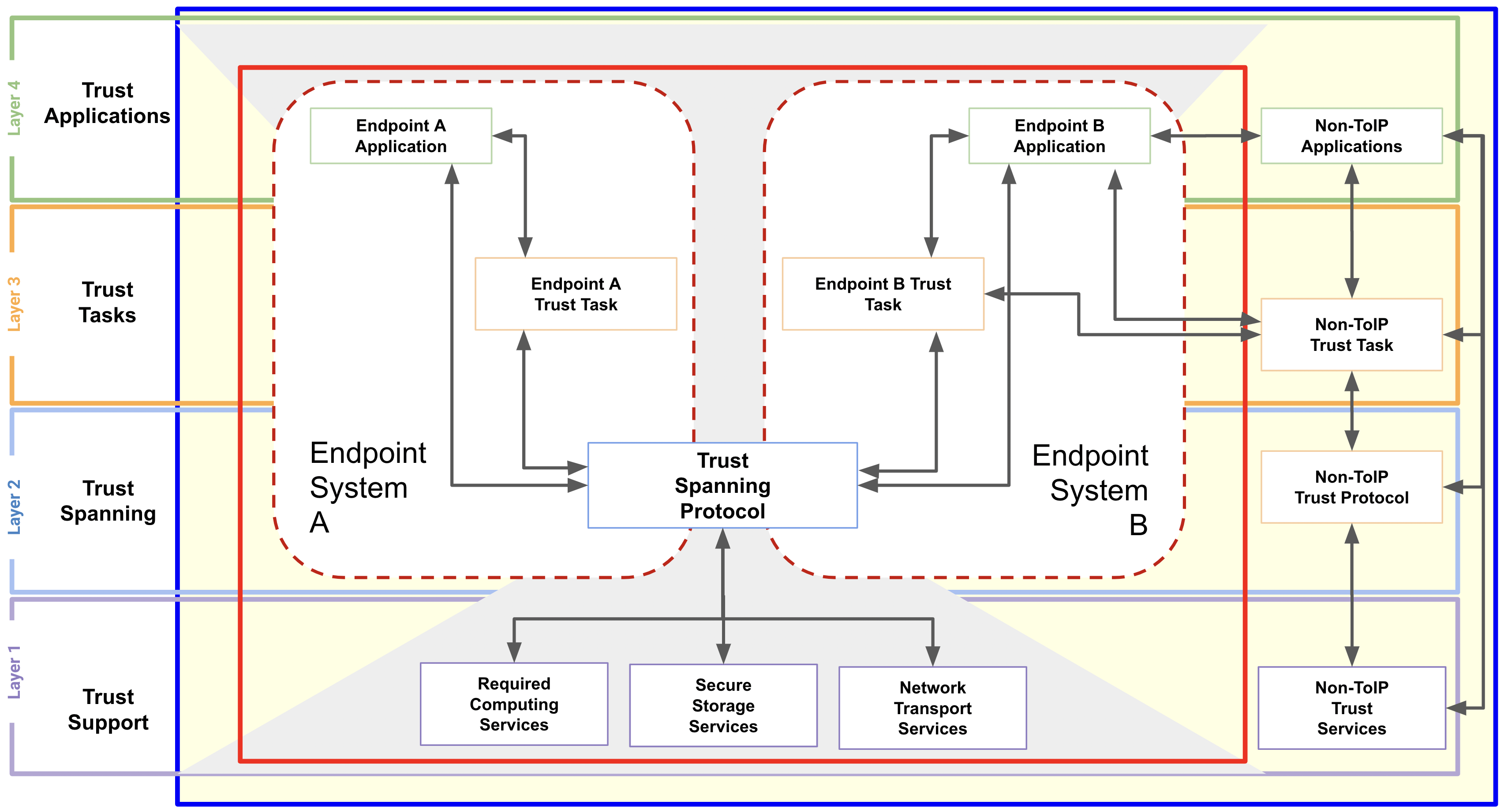
- endpoint system:
-
The system that operates a communications endpoint. In the context of the ToIP stack, an endpoint system is one of three types of systems defined in the ToIP Technology Architecture Specification.
- enterprise data vault:
-
A digital vault whose controller is an organization.
- enterprise wallet:
-
A digital wallet whose holder is an organization.
- entity:
-
Someone or something that is known to exist.
- entity:
-
Someone or something that is known to exist.
- ephemeral connection:
-
A connection that only exists for the duration of a single communication session or transaction.
- expression language:
-
A language for creating a computer-interpretable (machine-readable) representation of specific knowledge.
- FAL:
-
See: federation assurance level.
- federated identity:
-
A digital identity architecture in which a digital identity established on one computer system, network, or trust domain is linked to other computer systems, networks, or trust domains for the purpose of identifying the same entity across those domains.
- federation:
-
A group of organizations that collaborate to establish a common trust framework or governance framework for the exchange of identity data in a federated identity system.
- federation assurance level:
-
A category that describes the federation protocol used to communicate an assertion containing authentication) and attribute information (if applicable) to a relying party, as defined in NIST SP 800-63-3 in terms of three levels: FAL 1 (Some confidence), FAL 2 (High confidence), FAL 3 (Very high confidence).
- fiduciary:
-
A fiduciary is a person who holds a legal or ethical relationship of trust with one or more other parties (person or group of persons). Typically, a fiduciary prudently takes care of money or other assets for another person. One party, for example, a corporate trust company or the trust department of a bank, acts in a fiduciary capacity to another party, who, for example, has entrusted funds to the fiduciary for safekeeping or investment. In a fiduciary relationship, one person, in a position of vulnerability, justifiably vests confidence, good faith, reliance, and trust in another whose aid, advice, or protection is sought in some matter.
- first party:
-
The party who initiates a trust relationship, connection, or transaction with a second party.
- foundational identity:
-
A set of identity data, such as a credential, issued by an authoritative source for the legal identity of the subject. Birth certificates, passports, driving licenses, and other forms of government ID documents are considered foundational identity documents. Foundational identities are often used to provide identity binding for functional identities.
- fourth party:
-
A party that is not directly involved in the trust relationship between a first party and a second party, but provides supporting services exclusively to the first party (in contrast with a third party, who in most cases provides supporting services to the second party). In its strongest form, a fourth party has a fiduciary relationship with the first party.
- functional identity:
-
A set of identity data, such as a credential, that is issued not for the purpose of establishing a foundational identity for the subject, but for the purpose of establishing other attributes, qualifications, or capabilities of the subject. Loyalty cards, library cards, and employee IDs are all examples of functional identities. Foundational identities are often used to provide identity binding for functional identities.
- gateway:
-
A gateway is a piece of networking hardware or software used in telecommunications networks that allows data to flow from one discrete network to another. Gateways are distinct from routers or switches in that they communicate using more than one protocol to connect multiple networks[1][2] and can operate at any of the seven layers of the open systems interconnection model (OSI).
- GDPR:
-
See: General Data Protection Regulation.
- General Data Protection Regulation:
-
The General Data Protection Regulation (Regulation (EU) 2016/679, abbreviated GDPR) is a European Union regulation on information privacy in the European Union (EU) and the European Economic Area (EEA). The GDPR is an important component of EU privacy law and human rights law, in particular Article 8(1) of the Charter of Fundamental Rights of the European Union. It also governs the transfer of personal data outside the EU and EEA. The GDPR’s goals are to enhance individuals’ control and rights over their personal information and to simplify the regulations for international business.
- glossary:
-
A glossary (from Ancient Greek: γλῶσσα, glossa; language, speech, wording), also known as a vocabulary or clavis, is an alphabetical list of terms in a particular domain of knowledge (scope) together with the definitions for those terms. Unlike a dictionary, a glossary has only one definition for each term.
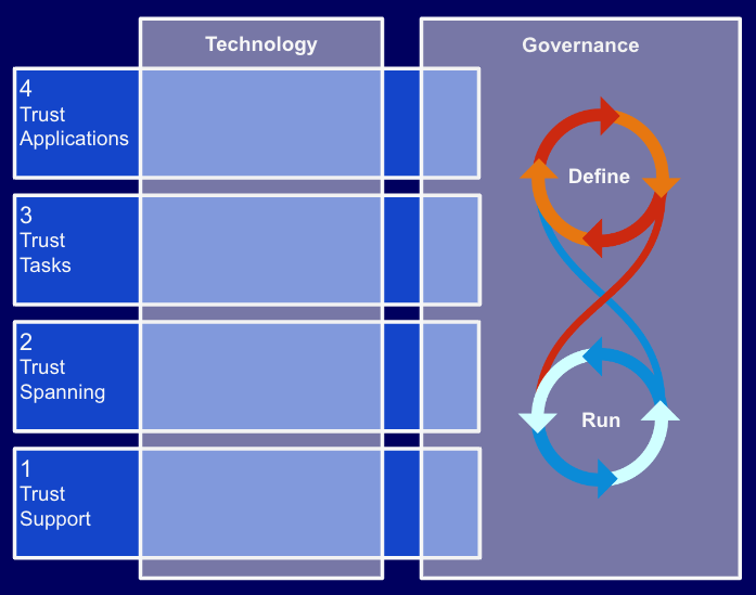
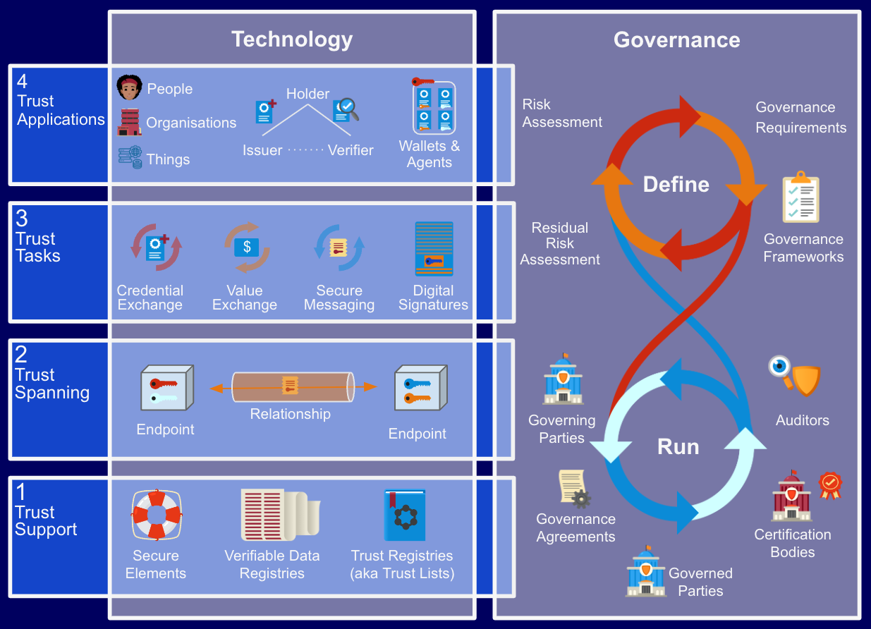
- Governance:
-
Governance, risk management, and compliance (GRC) are three related facets that aim to assure an organization reliably achieves objectives, addresses uncertainty and acts with integrity. Governance is the combination of processes established and executed by the directors (or the board of directors) that are reflected in the organization's structure and how it is managed and led toward achieving goals. Risk management is predicting and managing risks that could hinder the organization from reliably achieving its objectives under uncertainty. Compliance refers to adhering with the mandated boundaries (laws and regulations) and voluntary boundaries (company’s policies, procedures, etc.)
- governance diamond:
-
A term that refers to the addition of a governing body to the standard trust triangle of issuers, holders, and verifiers of credentials. The resulting combination of four parties represents the basic structure of a digital trust ecosystem.
- governance document:
-
A document with at least one identifier that specifies governance requirements for a trust community.
- governance framework:
-
A collection of one or more governance documents published by the governing body of a trust community.
- governance graph:
-
A graph of the governance relationships between entities with a trust community. A governance graph shows which nodes are the governing bodies and which are the governed parties. In some cases, a governance graph can be traversed by making queries to one or more trust registries.Note: a party can play both roles and also be a participant in multiple governance frameworks.
- governance requirement:
-
A requirement such as a policy, rule, or technical specification specified in a governance document.
- governed use case:
-
A use case specified in a governance document that results in specific governance requirements within that governance framework. Governed use cases may optionally be discovered via a trust registry authorized by the relevant governance framework.
- governed party:
-
A party whose role(s) in a trust community is governed by the governance requirements in a governance framework.
- governed party:
-
A party whose role(s) in a trust community is governed by the governance requirements in a governance framework.
- governed information:
-
Any information published under the authority of a governing body for the purpose of governing a trust community. This includes its governance framework and any information available via an authorized trust registry.
- governing authority:
-
See: governing body.
- governing body:
-
The party (or set of parties) authoritative for governing a trust community, usually (but not always) by developing, publishing, maintaining, and enforcing a governance framework. A governing body may be a government, a formal legal entity of any kind, an informal group of any kind, or an individual. A governing body may also delegate operational responsibilities to an administering body.
- GRC:
-
See: Governance.
- guardian:
-
A party that has been assigned rights and duties in a guardianship arrangement for the purpose of caring for, protecting, guarding, and defending the entity that is the dependent in that guardianship arrangement. In the context of decentralized digital trust infrastructure, a guardian is issued guardianship credentials into their own digital wallet in order to perform such actions on behalf of the dependent as are required by this role.
- guardianship arrangement:
-
A guardianship arrangement (in a jurisdiction) is the specification of a set of rights and duties between legal entities of the jurisdiction that enforces these rights and duties, for the purpose of caring for, protecting, guarding, and defending one or more of these entities. At a minimum, the entities participating in a guardianship arrangement are the guardian and the dependent.
- guardianship credential:
-
A digital credential issued by a governing body to a guardian to empower the guardian to undertake the rights and duties of a guardianship arrangement on behalf of a dependent.
- hardware security module:
-
A physical computing device that provides tamper-evident and intrusion-resistant safeguarding and management of digital keys and other secrets, as well as crypto-processing.
- hash:
-
The result of applying a hash function to a message.
- hash function:
-
An algorithm that computes a numerical value (called the hash value) on a data file or electronic message that is used to represent that file or message, and depends on the entire contents of the file or message. A hash function can be considered to be a fingerprint of the file or message. Approved hash functions satisfy the following properties: one-way (it is computationally infeasible to find any input that maps to any pre-specified output); and collision resistant (it is computationally infeasible to find any two distinct inputs that map to the same output).
- holder (of a claim or credential):
-
A role an agent performs by serving as the controller of the cryptographic keys and digital credentials in a digital wallet. The holder makes issuance requests for credentials and responds to presentation requests for credentials. A holder is usually, but not always, a subject of the credentials they are holding.
- holder binding:
-
The process of creating and verifying a relationship between the holder of a digital wallet and the wallet itself. Holder binding is related to but NOT the same as subject binding.
- host:
-
A host is any hardware device that has the capability of permitting access to a network via a user interface, specialized software, network address, protocol stack, or any other means. Some examples include, but are not limited to, computers, personal electronic devices, thin clients, and multi-functional devices.
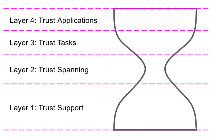
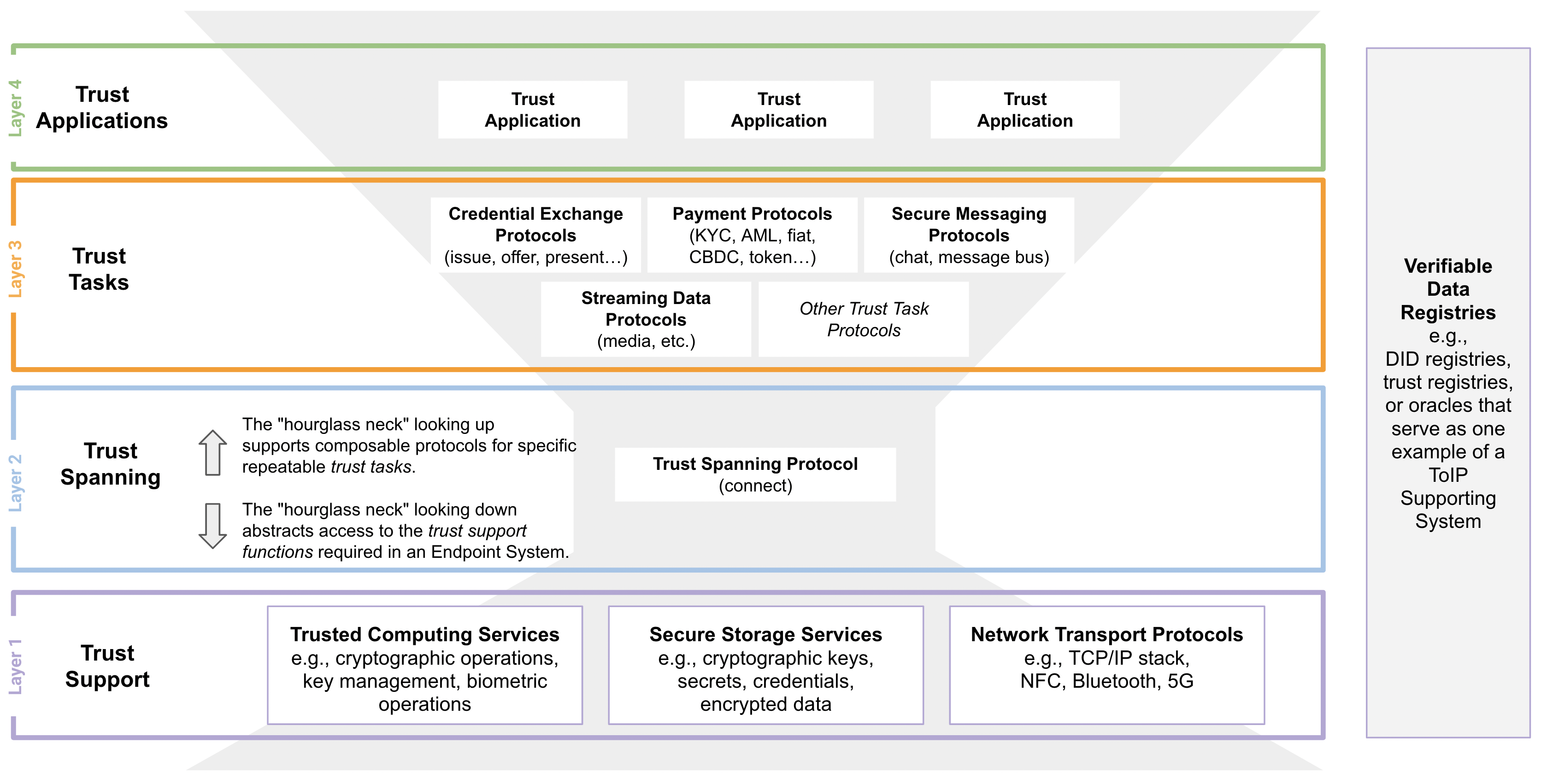
- hourglass model:
-
An architectural model for layered systems—and specifically for the protocol layers in a protocol stack—in which a diversity of supporting protocols and services at the lower layers are able to support a great diversity of protocols and applications at the higher layers through the use of a single protocol in the spanning layer in the middle—the “neck” of the hourglass.
- HSM:
-
See: hardware security module.
- human auditability:
-
See: human auditable.
- human auditable:
-
A process or procedure whose compliance with the policies in a trust framework or governance framework can only be verified by a human performing an audit. Human auditability is a primary goal of the ToIP Governance Stack.
- human experience:
-
The processes, patterns and rituals of acquiring knowledge or skill from doing, seeing, or feeling things as a natural person. In the context of decentralized digital trust infrastructure, the direct experience of a natural person using trust applications to make trust decisions within one or more digital trust ecosystems.
- human-readable:
-
Information that can be processed by a human but that is not intended to be machine-readable.
- human trust:
-
A level of assurance in a trust relationship that can be achieved only via human evaluation of applicable trust factors.
- IAL:
-
See: identity assurance level.
- identification:
-
The action of a party obtaining the set of identity data necessary to serve as that party’s identity for a specific entity.
- identifier:
-
A single attribute—typically a character string—that uniquely identifies an entity within a specific context (which may be a global context). Examples include the name of a party the URL of an organization, or a serial number for a man-made thing.
- identity:
-
A collection of attributes or other identity data that describe an entity and enable it to be distinguished from all other entities within a specific scope of identification. Identity attributes may include one or more identifiers for an entity, however it is possible to establish an identity without using identifiers.
- identity assurance level:
-
A category that conveys the degree of confidence that a person’s claimed identity is their real identity, for example as defined in NIST SP 800-63-3 in terms of three levels: IAL 1 (Some confidence), IAL 2 (High confidence), IAL 3 (Very high confidence).
- identity binding:
-
The process of associating a set of identity data, such as a credential, with its subject, such as a natural person. The strength of an identity binding is one factor in determining an authenticator assurance level.
- identity data:
-
The set of data held by a party in order to provide an identity for a specific entity.
- identity document:
-
A physical or digital document containing identity data. A credential is a specialized form of identity document. Birth certificates, bank statements, and utility bills can all be considered identity documents.
- identity proofing:
-
The process of a party gathering sufficient identity data to establish an identity for a particular subject at a particular identity assurance level.
- identity provider:
-
An identity provider (abbreviated IdP or IDP) is a system entity that creates, maintains, and manages identity information for principals and also provides authentication services to relying applications within a federation or distributed network.
- IDP:
-
See: identity provider.
- impersonation:
-
In the context of cybersecurity, impersonation is when an attacker pretends to be another person in order to commit fraud or some other digital crime.
- integrity (of a data structure):
-
In IT security, data integrity means maintaining and assuring the accuracy and completeness of data over its entire lifecycle. This means that data cannot be modified in an unauthorized or undetected manner.
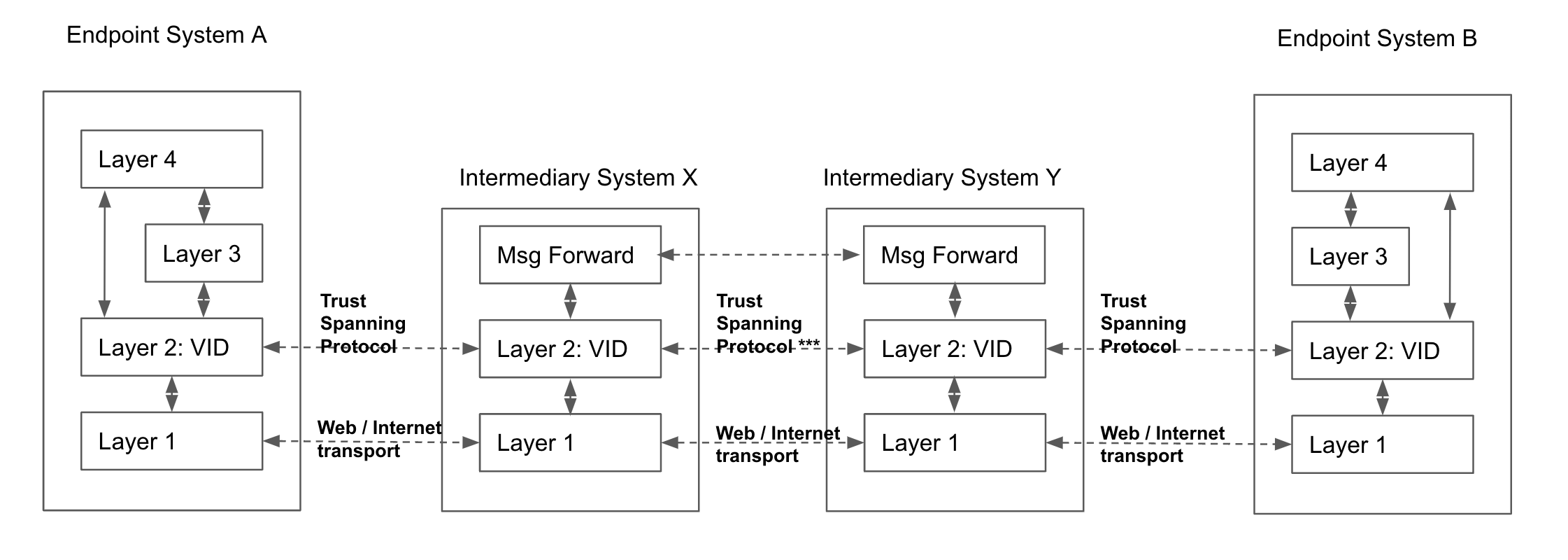
- intermediary system:
-
A system that operates at ToIP Layer 2, the trust spanning layer of the ToIP stack, in order to route ToIP messages between endpoint systems. A supporting system is one of three types of systems defined in the ToIP Technology Architecture Specification.
- Internet Protocol:
-
The Internet Protocol (IP) is the network layer communications protocol in the Internet protocol suite (also known as the TCP/IP suite) for relaying datagrams across network boundaries. Its routing function enables internetworking, and essentially establishes the Internet. IP has the task of delivering packets from the source host to the destination host solely based on the IP addresses in the packet headers. For this purpose, IP defines packet structures that encapsulate the data to be delivered. It also defines addressing methods that are used to label the datagram with source and destination information.
- Internet protocol suite:
-
The Internet protocol suite, commonly known as TCP/IP, is a framework for organizing the set of communication protocols used in the Internet and similar computer networks according to functional criteria. The foundational protocols in the suite are the Transmission Control Protocol (TCP), the User Datagram Protocol (UDP), and the Internet Protocol (IP).
- IP:
-
See: Internet Protocol.
- IP address:
-
An Internet Protocol address (IP address) is a numerical label such as 192.0.2.1 that is connected to a computer network that uses the Internet Protocol for communication. An IP address serves two main functions: network interface identification, and location addressing.
- issuance:
-
The action of an issuer producing and transmitting a digital credential to a holder. A holder may request issuance by submitting an issuance request.
- issuance request:
-
A protocol request invoked by the holder of a digital wallet to obtain a digital credential from an issuer.
- issuer (of a claim or credential):
-
A role an agent performs to package and digitally sign a set of claims, typically in the form of a digital credential, and transmit them to a holder.
- jurisdiction:
-
The composition of: a) a legal system (legislation, enforcement thereof, and conflict resolution), b) a party that governs that legal system, c) a scope within which that legal system is operational, and d) one or more objectives for the purpose of which the legal system is operated.
- KATE:
-
See: keys-at-the-edge.
- KERI:
-
See: Key Event Receipt Infrastructure.
- key:
-
See: cryptographic key.
- key establishment:
-
A process that results in the sharing of a key between two or more entities, either by transporting a key from one entity to another (key transport) or generating a key from information shared by the entities (key agreement).
- key event:
-
An event in the history of the usage of a cryptographic key pair. There are multiple types of key events. The inception event is when the key pair is first generated. A rotation event is when the key pair is changed to a new key pair. In some key management systems (such as KERI), key events are tracked in a key event log.
- key event log:
-
An ordered sequence of records of key events.
- Key Event Receipt Infrastructure:
-
A decentralized permissionless key management architecture.
- key management system:
-
A system for the management of cryptographic keys and their metadata (e.g., generation, distribution, storage, backup, archive, recovery, use, revocation, and destruction). An automated key management system may be used to oversee, automate, and secure the key management process. A key management is often protected by implementing it within the trusted execution environment (TEE) of a device. An example is the Secure Enclave on Apple iOS devices.
- keys-at-the-edge:
-
A key management architecture in which keys are stored on a user’s local edge devices, such as a smartphone, tablet, or laptop, and then used in conjunction with a secure protocol to unlock a key management system (KMS) and/or a digital vault in the cloud. This approach can enable the storage and sharing of large data structures that are not feasible on edge devices. This architecture can also be used in conjunction with confidential computing to enable cloud-based digital agents to safely carry out “user not present” operations.
- KMS:
-
See: key management system.
- knowledge:
-
The (intangible) sum of what is known by a specific party, as well as the familiarity, awareness or understanding of someone or something by that party.
- Laws of Identity:
-
A set of seven “laws” written by Kim Cameron, former Chief Identity Architect of Microsoft (1941-2021), to describe the dynamics that cause digital identity systems to succeed or fail in various contexts. His goal was to define the requirements for a unifying identity metasystem that can offer the Internet the identity layer it needs.
- Layer 1:
-
See: ToIP Layer 1.
- Layer 2:
-
See: ToIP Layer 2.
- Layer 3:
-
See: ToIP Layer 3.
- Layer 4:
-
See: ToIP Layer 4.
- legal entity:
-
An entity that is not a natural person but is recognized as having legal rights and responsibilities. Examples include corporations, partnerships, sole proprietorships, non-profit organizations, associations, and governments. (In some cases even natural systems such as rivers are treated as legal entities.)
- Legal Entity Identifier:
-
The Legal Entity Identifier (LEI) is a unique global identifier for legal entities participating in financial transactions. Also known as an LEI code or LEI number, its purpose is to help identify legal entities on a globally accessible database. Legal entities are organisations such as companies or government entities that participate in financial transactions.
- legal identity:
-
A set of identity data considered authoritative to identify a party for purposes of legal accountability under one or more jurisdictions.
- legal person:
-
In law, a legal person is any person or ‘thing’ that can do the things a human person is usually able to do in law – such as enter into contracts, sue and be sued, own property, and so on.[3][4][5] The reason for the term “legal person” is that some legal persons are not people: companies and corporations are “persons” legally speaking (they can legally do most of the things an ordinary person can do), but they are not people in a literal sense (human beings).
- legal system:
-
A system in which policies and rules are defined, and mechanisms for their enforcement and conflict resolution are (implicitly or explicitly) specified. Legal systems are not just defined by governments; they can also be defined by a governance framework.
- LEI:
-
See: Legal Entity Identifier.
- level of assurance:
-
See: assurance level.
- liveness detection:
-
Any technique used to detect a presentation attack by determining whether the source of a biometric sample is a live human being or a fake representation. This is typically accomplished using algorithms that analyze biometric sensor data to detect whether the source is live or reproduced.
- locus of control:
-
The set of computing systems under a party’s direct control, where messages and data do not cross trust boundaries.
- machine-readable:
-
Information written in a computer language or expression language so that it can be read and processed by a computing device.
- man-made thing:
-
Athing generated by human activity of some kind. Man-made things include both active things, such as cars or drones, and passive things, such as chairs or trousers.
- mandatory:
-
A requirement that must be implemented in order for an implementer to be in compliance. In ToIP governance frameworks, a mandatory requirement is expressed using a MUST or REQUIRED keyword as defined in IETF RFC 2119.
- metadata:
-
Information describing the characteristics of data including, for example, structural metadata describing data structures (e.g., data format, syntax, and semantics) and descriptive metadata describing data contents (e.g., information security labels).
- message:
-
A discrete unit of communication intended by the source for consumption by some recipient or group of recipients.
- mobile deep link:
-
In the context of mobile apps, deep linking consists of using a uniform resource identifier (URI) that links to a specific location within a mobile app rather than simply launching the app. Deferred deep linking allows users to deep link to content even if the app is not already installed. Depending on the mobile device platform, the URI required to trigger the app may be different.
- MPC:
-
See: multi-party computation.
- multicast:
-
In computer networking, multicast is group communication where data transmission is addressed (using a multicast address) to a group of destination computers simultaneously. Multicast can be one-to-many or many-to-many distribution. Multicast should not be confused with physical layer point-to-multipoint communication.
- multicast address:
-
A multicast address is a logical identifier for a group of hosts in a computer network that are available to process datagrams or frames intended to be multicast for a designated network service.
- multi-party computation:
-
Secure multi-party computation (also known as secure computation, multi-party computation (MPC) or privacy-preserving computation) is a subfield of cryptography with the goal of creating methods for parties to jointly compute a function over their inputs while keeping those inputs private. Unlike traditional cryptographic tasks, where cryptography assures security and integrity of communication or storage and the adversary is outside the system of participants (an eavesdropper on the sender and receiver), the cryptography in this model protects participants’ privacy from each other.
- multi-party control:
-
A variant of multi-party computation where multiple parties must act in concert to meet a control requirement without revealing each other’s data. All parties are privy to the output of the control, but no party learns anything about the others.
- multi-signature:
-
A cryptographic signature scheme where the process of signing information (e.g., a transaction) is distributed among multiple private keys.
- natural person:
-
A person (in legal meaning, i.e., one who has its own legal personality) that is an individual human being, distinguished from the broader category of a legal person, which may be a private (i.e., business entity or non-governmental organization) or public (i.e., government) organization.
- natural thing:
-
A thing that exists in the natural world independently of humans. Although natural things may form part of a man-made thing, natural things are mutually exclusive with man-made things.
- network address:
-
A network address is an identifier for a node or host on a telecommunications network. Network addresses are designed to be unique identifiers across the network, although some networks allow for local, private addresses, or locally administered addresses that may not be unique. Special network addresses are allocated as broadcast or multicast addresses. A network address designed to address a single device is called a unicast address.
- node:
-
In telecommunications networks, a node (Latin: nodus, ‘knot’) is either a redistribution point or a communication endpoint. The definition of a node depends on the network and protocol layer referred to. A physical network node is an electronic device that is attached to a network, and is capable of creating, receiving, or transmitting information over a communication channel.
- non-custodial wallet:
-
A digital wallet that is directly in the control of the holder, usually because the holder is the device controller of the device hosting the digital wallet (smartcard, smartphone, tablet, laptop, desktop, car, etc.) A digital wallet that is in the custody of a third party is called a custodial wallet.
- objective:
-
Something toward which a party (its owner) directs effort (an aim, goal, or end of action).
- OOBI:
-
See: out-of-band introduction.
- OpenWallet Foundation:
-
A non-profit project of the Linux Foundation chartered to build a world-class open source wallet engine.
- operational circumstances:
-
In the context of privacy protection, this term denotes the context in which privacy trade-off decisions are made. It includes the regulatory environment and other non-technical factors that bear on what reasonable privacy expectations might be.
- optional:
-
A requirement that is not mandatory or recommended to implement in order for an implementer to be in compliance, but which is left to the implementer’s choice. In ToIP governance frameworks, an optional requirement is expressed using a MAY or OPTIONAL keyword as defined in IETF RFC 2119.
- organization:
-
A party that consists of a group of parties who agree to be organized into a specific form in order to better achieve a common set of objectives. Examples include corporations, partnerships, sole proprietorships, non-profit organizations, associations, and governments.
- organizational authority:
-
A type of authority where the party asserting its right is an organization.
- out-of-band introduction
-
A process by which two or more entities exchange VIDs in order to form a cryptographically verifiable connection (e.g., a ToIP connection), such as by scanning a QR code (in person or remotely) or clicking a deep link.
- out-of-band introduction
-
A process by which two or more entities exchange VIDs in order to form a cryptographically verifiable connection (e.g., a ToIP connection), such as by scanning a QR code (in person or remotely) or clicking a deep link.
- owner (of an entity):
-
The role that a party performs when it is exercising its legal, rightful or natural title to control a specific entity.
- P2P:
-
See: peer-to-peer.
- party:
-
An entity that sets its objectives, maintains its knowledge, and uses that knowledge to pursue its objectives in an autonomous (sovereign) manner. Humans and organizations are the typical examples.
- password:
-
A string of characters (letters, numbers and other symbols) that are used to authenticate an identity, verify access authorization or derive cryptographic keys.
- peer:
-
In the context of digital networks, an actor on the network that has the same status, privileges, and communications options as the other actors on the network.
- peer-to-peer:
-
Peer-to-peer (P2P) computing or networking is a distributed application architecture that partitions tasks or workloads between peers. Peers are equally privileged, equipotent participants in the network. This forms a peer-to-peer network of nodes.
- permission
-
Authorization to perform some action on a system.
- persistent connection:
-
A connection that is able to persist across multiple communication sessions. In a ToIP context, a persistent connection is established when two ToIP endpoints exchange verifiable identifiers that they can use to re-establish the connection with each other whenever it is needed.
- personal data:
-
Any information relating to an identified or identifiable natural person (called a data subject under GDPR).
- personal data store:
-
See: personal data vault.
- personal data vault:
-
A digital vault whose controller is a natural person.
- personal wallet:
-
A digital wallet whose holder is a natural person.
- personally identifiable information:
-
Information (any form of data) that can be used to directly or indirectly identify or re-identify an individual person either singly or in combination within a single record or in correlation with other records. This information can be one or more attributes/fields/properties in a record (e.g., date-of-birth) or one or more records (e.g., medical records).
- physical credential:
-
A credential in a physical form such as paper, plastic, or metal.
- PII:
-
See: personally identifiable information.
- PKI:
-
See: public key infrastructure.
- plaintext:
-
Unencrypted information that may be input to an encryption operation. Once encrypted, it becomes ciphertext.
- policy
-
Statements, rules or assertions that specify the correct or expected behavior of an entity.
- PoP:
-
See: proof of personhood.
- presentation:
-
A verifiable message that a holder may send to a verifier containing proofs of one or more claims derived from one or more digital credentials from one or more issuers as a response to a specific presentation request from a verifier.
- presentation attack:
-
A type of cybersecurity attack in which the attacker attempts to defeat a biometric liveness detection system by providing false inputs.
- presentation request:
-
A protocol request sent by the verifier to the holder of a digital wallet to request a presentation.
- primary document:
-
The governance document at the root of a governance framework. The primary document specifies the other controlled documents in the governance framework.
- principal:
-
The party for whom, or on behalf of whom, an actor is executing an action (this actor is then called an agent of that party).
- Principles of SSI:
-
A set of principles for self-sovereign identity systems originally defined by the Sovrin Foundation and republished by the ToIP Foundation.
- privacy policy:
-
A statement or legal document (in privacy law) that discloses some or all of the ways a party gathers, uses, discloses, and manages a customer or client’s data.
- private key:
-
In public key cryptography, the cryptographic key which must be kept secret by the controller in order to maintain security.
- proof:
-
A digital object that enables cryptographic verification of either: a) the claims from one or more digital credentials, or b) facts about claims that do not reveal the data itself (e.g., proof of the subject being over/under a specific age without revealing a birthdate).
- proof of control:
-
See: proof of possession.
- proof of personhood:
-
Proof of personhood (PoP) is a means of resisting malicious attacks on peer-to-peer networks, particularly, attacks that utilize multiple fake identities, otherwise known as a Sybil attack. Decentralized online platforms are particularly vulnerable to such attacks by their very nature, as notionally democratic and responsive to large voting blocks. In PoP, each unique human participant obtains one equal unit of voting power, and any associated rewards.
- proof of possession:
-
A verification process whereby a level of assurance is obtained that the owner of a key pair actually controls the private key associated with the public key.
- proof of presence:
-
See: liveness detection.
- property:
-
In the context of digital communication, an attribute of a digital object or data structure, such as a DID document or a schema.
- protected data:
-
Data that is not publicly available but requires some type of access control to gain access.
- protocol layer:
-
In modern protocol design, protocols are layered to form a protocol stack. Layering is a design principle that divides the protocol design task into smaller steps, each of which accomplishes a specific part, interacting with the other parts of the protocol only in a small number of well-defined ways. Layering allows the parts of a protocol to be designed and tested without a combinatorial explosion of cases, keeping each design relatively simple.
- protocol stack:
-
The protocol stack or network stack is an implementation of a computer networking protocol suite or protocol family. Some of these terms are used interchangeably but strictly speaking, the suite is the definition of the communication protocols, and the stack is the software implementation of them.
- pseudonym:
-
A pseudonym is a fictitious name that a person assumes for a particular purpose, which differs from their original or true name (orthonym). This also differs from a new name that entirely or legally replaces an individual’s own. Many pseudonym holders use pseudonyms because they wish to remain anonymous, but anonymity is difficult to achieve and often fraught with legal issues.
- public key:
-
Drummond Reed: In public key cryptography, the cryptographic key that can be freely shared with anyone by the controller without compromising security. A party’s public key must be verified as authoritative in order to verify their digital signature.
- public key certificate:
-
A set of data that uniquely identifies a public key (which has a corresponding private key) and an owner that is authorized to use the key pair. The certificate contains the owner’s public key and possibly other information and is digitally signed by a certification authority (i.e., a trusted party), thereby binding the public key to the owner.
- public key cryptography:
-
Public key cryptography, or asymmetric cryptography, is the field of cryptographic systems that use pairs of related keys. Each key pair consists of a public key and a corresponding private key. Key pairs are generated with cryptographic algorithms based on mathematical problems termed one-way functions. Security of public key cryptography depends on keeping the private key secret; the public key can be openly distributed without compromising security.
- public key infrastructure:
-
A set of policies, processes, server platforms, software and workstations used for the purpose of administering certificates and public-private key pairs, including the ability to issue, maintain, and revoke public key certificates. The PKI includes the hierarchy of certificate authorities that allow for the deployment of digital certificates that support encryption, digital signature and authentication to meet business and security requirements.
- QR code:
-
A QR code (short for “quick-response code”) is a type of two-dimensional matrix barcode—a machine-readable optical image that contains information specific to the identified item. In practice, QR codes contain data for a locator, an identifier, and web tracking.
- RBAC:
-
See: role-based access control.
- real world identity
-
A term used to describe the opposite of digital identity, i.e., an identity (typically for a person) in the physical instead of the digital world.
- recommended:
-
A requirement that is not mandatory to implement in order for an implementer to be in compliance, but which should be implemented unless the implementer has a good reason. In ToIP governance frameworks, a recommendation is expressed using a SHOULD or RECOMMENDED keyword as defined in IETF RFC 2119.
- record:
-
A uniquely identifiable entry or listing in a database or registry.
- registrant:
-
The party submitting a registration record to a registry.
- registrar:
-
The party who performs registration on behalf of a registrant.
- registration:
-
The process by which a registrant submits a record to a registry.
- registry:
-
A specialized database of records that serves as an authoritative source of information about entities.
- relationship context:
-
A context established within the boundary of a trust relationship.
- relying party:
-
A party who consumes claims or trust graphs from other parties (such as issuers, holders, and trust registries) in order to make a trust decision.
- reputation:
-
The reputation or prestige of a social entity (a person, a social group, an organization, or a place) is an opinion about that entity – typically developed as a result of social evaluation on a set of criteria, such as behavior or performance.
- reputation graph:
-
A graph of the reputation relationships between different entities in a trust community. In a digital trust ecosystem, the governing body may be one trust root of a reputation graph. In some cases, a reputation graph can be traversed by making queries to one or more trust registries.
- reputation system:
-
Reputation systems are programs or algorithms that allow users to rate each other in online communities in order to build trust through reputation. Some common uses of these systems can be found on e-commerce websites such as eBay, Amazon.com, and Etsy as well as online advice communities such as Stack Exchange.
- requirement:
-
A specified condition or behavior to which a system needs to comply. Technical requirements are defined in technical specifications and implemented in computer systems to be executed by software actors. Governance requirements are defined in governance documents that specify policies and procedures to be executed by human actors. In ToIP architecture, requirements are expressed using the keywords defined in Internet RFC 2119.
- revocation:
-
In the context of digital credentials, revocation is an event signifying that the issuer no longer attests to the validity of a credential they have issued. In the context of cryptographic keys, revocation is an event signifying that the controller no longer attests to the validity of a public/private key pair for which the controller is authoritative.
- risk:
-
The effects that uncertainty (i.e. a lack of information, understanding or knowledge of events, their consequences or likelihoods) can have on the intended realization of an objectiveof a party.
- risk assessment:
-
The process of identifying risks to organizational operations (including mission, functions, image, reputation), organizational assets, individuals, other organizations, and the overall ecosystem, resulting from the operation of an information system. Risk assessment is part of risk management, incorporates threat and vulnerability analyses, and considers risk mitigations provided by security controls planned or in place.
- risk decision:
-
See: trust decision.
- risk management:
-
The process of managing risks to organizational operations (including mission, functions, image, or reputation), organizational assets, or individuals resulting from the operation of an information system, and includes: (i) the conduct of a risk assessment; (ii) the implementation of a risk mitigation strategy; and (iii) employment of techniques and procedures for the continuous monitoring of the security state of the information system.
- risk mitigation:
-
Prioritizing, evaluating, and implementing the appropriate risk-reducing controls/countermeasures recommended from the risk management process.
- role:
-
A defined set of characteristics that an entity has in some context, such as responsibilities it may have, actions (behaviors) it may execute, or pieces of knowledge that it is expected to have in that context, which are referenced by a specific role name.
- role-based access control:
-
Access control based on user roles (i.e., a collection of access authorizations a user receives based on an explicit or implicit assumption of a given role). Role permissions may be inherited through a role hierarchy and typically reflect the permissions needed to perform defined functions within an organization. A given role may apply to a single individual or to several individuals.
- role credential:
-
A credential claiming that the subject has a specific role.
- router:
-
A router is a networking device that forwards data packets between computer networks. Routers perform the traffic directing functions between networks and on the global Internet. Data sent through a network, such as a web page or email, is in the form of data packets. A packet is typically forwarded from one router to another router through the networks that constitute an internetwork (e.g. the Internet) until it reaches its destination node. This process is called routing.
- routing:
-
Routing is the process of selecting a path for traffic in a network or between or across multiple networks. Broadly, routing is performed in many types of networks, including circuit-switched networks, such as the public switched telephone network (PSTN), and computer networks, such as the Internet. A router is a computing device that specializes in performing routing.
- rule:
-
A prescribed guide for conduct, process or action to achieve a defined result or objective. Rules may be human-readable or machine-readable or both.
- RWI:
-
See: real world identity.
- schema:
-
A framework, pattern, or set of rules for enforcing a specific structure on a digital object or a set of digital data. There are many types of schemas, e.g., data schema, credential verification schema, database schema.
- scope:
-
In the context of terminology, scope refers to the set of possible concepts within which: a) a specific term is intended to uniquely identify a concept, or b) a specific glossary is intended to identify a set of concepts. In the context of identification, scope refers to the set of possible entities within which a specific entity must be uniquely identified. In the context of specifications, scope refers to the set of problems (the problem space) within which the specification is intended to specify solutions.
- SCID:
-
See: self-certifying identifier.
- second party:
-
The party with whom a first party engages to form a trust relationship, establish a connection, or execute a transaction.
- Secure Enclave:
-
A coprocessor on Apple iOS devices that serves as a trusted execution environment.
- secure multi-party computation:
-
See: multi-party computation.
- Secure Sockets Layer:
-
The original transport layer security protocol developed by Netscape and partners. Now deprecated in favor of Transport Layer Security (TLS).
- security domain:
-
An environment or context that includes a set of system resources and a set of system entities that have the right to access the resources as defined by a common security policy, security model, or security architecture.
- security policy:
-
A set of policies and rules that governs all aspects of security-relevant system and system element behavior.
- self-asserted:
-
A term used to describe a claim or a credential whose subject is also the issuer.
- self-certified:
-
When a party provides its own certification that it is compliant with a set of requirements, such as a governance framework.
- self-certifying identifier
-
A subclass of verifiable identifier that is cryptographically verifiable without the need to rely on any third party for verification because the identifier is cryptographically bound to the cryptographic keys from which it was generated.
~ Also known as: autonomous identifier.
- self-sovereign identity:
-
A decentralized identity architecture that implements the Principles of SSI.
- sensitive data:
-
Personal data that a reasonable person would view from a privacy protection standpoint as requiring special care above and beyond other personal data.
- session:
-
See: communication session.
- sociotechnical system:
-
An approach to complex organizational work design that recognizes the interaction between people and technology in workplaces. The term also refers to coherent systems of human relations, technical objects, and cybernetic processes that inhere to large, complex infrastructures. Social society, and its constituent substructures, qualify as complex sociotechnical systems.
- software agent:
-
In computer science, a software agent is a computer program that acts for a user or other program in a relationship of agency, which derives from the Latin agere (to do): an agreement to act on one’s behalf. A user agent is a specific type of software agent that is used directly by an end-user as the principal.
- Sovrin Foundation:
-
A 501 ©(4) nonprofit organization established to administer the governance framework governing the Sovrin Network, a public service utility enabling self-sovereign identity on the internet. The Sovrin Foundation is an independent organization that is responsible for ensuring the Sovrin identity system is public and globally accessible.
- spanning layer:
-
A specific layer within a protocol stack that consists of a single protocol explicitly designed to provide interoperability between the protocols layers above it and below it.
- specification:
-
See: technical specification.
- SSI:
-
See: self-sovereign identity.
- SSL:
-
See: Secure Sockets Layer.
- stream:
-
In the context of digital communications, and in particular streaming media, a flow of data delivered in a continuous manner from a server to a client rather than in discrete messages.
- streaming media:
-
Streaming media is multimedia for playback using an offline or online media player. Technically, the stream is delivered and consumed in a continuous manner from a client, with little or no intermediate storage in network elements. Streaming refers to the delivery method of content, rather than the content itself.
- subject:
-
The entity described by one or more claims, particularly in the context of digital credentials.
- subscription:
-
In the context of decentralized digital trust infrastructure, a subscription is an agreement between a first digital agent—the publisher—to automatically send a second digital agent—the subscriber—a message when a specific type of event happens in the wallet or vault managed by the first digital agent.
- supporting system:
-
A system that operates at ToIP Layer 1, the trust support layer of the ToIP stack. A supporting system is one of three types of systems defined in the ToIP Technology Architecture Specification.
- Sybil attack:
-
A Sybil attack is a type of attack on a computer network service in which an attacker subverts the service’s reputation system by creating a large number of pseudonymous identities and uses them to gain a disproportionately large influence. It is named after the subject of the book Sybil, a case study of a woman diagnosed with dissociative identity disorder.
- system of record:
-
A system of record (SOR) or source system of record (SSoR) is a data management term for an information storage system (commonly implemented on a computer system running a database management system) that is the authoritative data source for a given data element or piece of information.
- tamper resistant:
-
A process which makes alterations to the data difficult (hard to perform), costly (expensive to perform), or both.
- TCP:
-
See: Transmission Control Protocol.
- TCP/IP:
-
See: Internet Protocol Suite.
- TCP/IP stack:
-
The protocol stack implementing the TCP/IP suite.
- technical requirement:
-
A requirement for a hardware or software component or system. In the context of decentralized digital trust infrastructure, technical requirements are a subset of governance requirements. Technical requirements are often specified in a technical specification.
- technical specification:
-
A document that specifies, in a complete, precise, verifiable manner, the requirements, design, behavior, or other characteristics of a system or component and often the procedures for determining whether these provisions have been satisfied.
- technical trust:
-
A level of assurance in a trust relationship that can be achieved only via technical means such as hardware, software, network protocols, and cryptography. Cryptographic trust is a specialized type of technical trust.
- TEE:
-
See: trusted execution environment.
- term:
-
A unit of text (i.e., a word or phrase) that is used in a particular context or scope to refer to a concept (or a relation between concepts, or a property of a concept).
- terminology:
-
Terminology is a group of specialized words and respective meanings in a particular field, and also the study of such terms and their use; the latter meaning is also known as terminology science. A term is a word, compound word, or multi-word expressions that in specific contexts is given specific meanings—these may deviate from the meanings the same words have in other contexts and in everyday language.[2] Terminology is a discipline that studies, among other things, the development of such terms and their interrelationships within a specialized domain. Terminology differs from lexicography, as it involves the study of concepts, conceptual systems and their labels (terms), whereas lexicography studies words and their meanings.
- :
-
A group of parties who share the need for a common terminology.
- terms wiki:
-
A wiki website used by a terms community to input, maintain, and publish its terminology. The ToIP Foundation Concepts and Terminology Working Group has established a simple template for GitHub-based terms wikis.
- thing:
-
An entity that is neither a natural person nor an organization and thus cannot be a party. A thing may be a natural thing or a man-made thing.
- third party:
-
A party that is not directly involved in the trust relationship between a first party and a second party, but provides supporting services to either or both of them.
- three party model:
-
The issuer—holder—verifier model used by all types of physical credentials and digital credentials to enable transitive trust decisions.
- timestamp:
-
A token or packet of information that is used to provide assurance of timeliness; the timestamp contains timestamped data, including a time, and a signature generated by a trusted timestamp authority (TTA).
- TLS:
-
See: Transport Layer Security.
- ToIP:
-
See: Trust Over IP
- ToIP application:
-
A trust application that runs at ToIP Layer 4, the trust application layer.
- ToIP channel:
-
See: VID relationship.
- ToIP communication:
-
Communication that uses the ToIP stack to deliver ToIP messages between ToIP endpoints, optionally using ToIP intermediaries, to provide authenticity, confidentiality, and correlation privacy.
- ToIP connection:
-
A connection formed using the ToIP Trust Spanning Protocol between two ToIP endpoints identified with verifiable identifiers. A ToIP connection is instantiated as one or more VID relationships.
- ToIP controller:
-
The controller of a ToIP identifier.
- ToIP Foundation:
-
A non-profit project of the Linux Foundation chartered to define an overall architecture for decentralized digital trust infrastructure known as the ToIP stack.
- ToIP endpoint:
-
An endpoint that communicates via the ToIP Trust Spanning Protocol as described in the ToIP Technology Architecture Specification.
- ToIP Governance Architecture Specification:
-
The specification defining the requirements for the ToIP Governance Stack published by the ToIP Foundation.
- ToIP governance framework:
-
A governance framework that conforms to the requirements of the ToIP Governance Architecture Specification.
- ToIP Governance Metamodel:
-
A structural model for ToIP governance frameworks that specifies the recommended governance documents that should be included depending on the objectives of the trust community.
- ToIP Governance Stack:
-
The governance half of the four layer ToIP stack as defined by the ToIP Governance Architecture Specification.
- ToIP identifier:
-
A verifiable identifier for an entity that is addressable using the ToIP stack.
- ToIP intermediary:
-
See: intermediary system.
- ToIP layer:
-
One of four protocol layers in the ToIP stack. The four layers are ToIP Layer 1, ToIP Layer 2, ToIP Layer 3, and ToIP Layer 4.
- ToIP Layer 1:
-
The trust support layer of the ToIP stack, responsible for supporting the trust spanning protocol at ToIP Layer 2.
- ToIP Layer 2:
-
The trust spanning layer of the ToIP stack, responsible for enabling the trust task protocols at ToIP Layer 3.
- ToIP Layer 3:
-
The trust task layer of the ToIP stack, responsible for enabling trust applications at ToIP Layer 4.
- ToIP Layer 4:
-
The trust application layer of the ToIP stack, where end users have the direct human experience of using applications that call trust task protocols to engage in trust relationships and make trust decisions using ToIP decentralized digital trust infrastructure.
- ToIP message:
-
A message communicated between ToIP endpoints using the ToIP stack.
- ToIP specification:
-
A specification published by the ToIP Foundation. Specifications may be in one of three states: Draft Deliverable, Working Group Approved Deliverable, or ToIP Approved Deliverables
- ToIP stack:
-
The layered architecture for decentralized digital trust infrastructure defined by the ToIP Foundation. The ToIP stack is a dual stack consisting of two halves: the ToIP Technology Stack and the ToIP Governance Stack. The four layers in the ToIP stack are ToIP Layer 1, ToIP Layer 2, ToIP Layer 3, and ToIP Layer 4.
- ToIP system:
-
A computing system that participates in the ToIP Technology Stack. There are three types of ToIP systems: endpoint systems, intermediary systems, and supporting systems.
- ToIP trust network:
-
A trust network implemented using the ToIP stack.
- ToIP Technology Architecture Specification:
-
The technical specification defining the requirements for the ToIP Technology Stack published by the ToIP Foundation.
- ToIP Technology Stack:
-
The technology half of the four layer ToIP stack as defined by the ToIP Technology Architecture Specification.
- :
-
A trust community governed by a ToIP governance framework.
- ToIP Trust Registry Protocol:
-
The open standard trust task protocol defined by the ToIP Foundation to perform the trust task of querying a trust registry. The ToIP Trust Registry Protocol operates at Layer 3 of the ToIP stack.
- ToIP Trust Spanning Protocol:
-
The ToIP Layer 2 protocol for verifiable messaging that implements the trust spanning layer of the ToIP stack. The ToIP Trust Spanning Protocol enables actors in different digital trust domains to interact in a similar way to how the Internet Protocol (IP) enables devices on different local area networks to exchange data.
- transaction:
-
A discrete event between a user and a system that supports a business or programmatic purpose. A digital system may have multiple categories or types of transactions, which may require separate analysis within the overall digital identity risk assessment.
- transitive trust decision:
-
A trust decision made by a first party about a second party or another entity based on information about the second party or the other entity that is obtained from one or more third parties.
- Transmission Control Protocol:
-
The Transmission Control Protocol (TCP) is one of the main protocols of the Internet protocol suite. It originated in the initial network implementation in which it complemented the Internet Protocol (IP). Therefore, the entire suite is commonly referred to as TCP/IP. TCP provides reliable, ordered, and error-checked delivery of a stream of octets (bytes) between applications running on hosts communicating via an IP network. Major internet applications such as the World Wide Web, email, remote administration, and file transfer rely on TCP, which is part of the Transport Layer of the TCP/IP suite. SSL/TLS often runs on top of TCP.
- Transport Layer Security:
-
Transport Layer Security (TLS) is a cryptographic protocol designed to provide communications security over a computer network. The protocol is widely used in applications such as email, instant messaging, and Voice over IP, but its use in securing HTTPS remains the most publicly visible. The TLS protocol aims primarily to provide security, including privacy (confidentiality), integrity, and authenticity through the use of cryptography, such as the use of certificates, between two or more communicating computer applications.
- tribal knowledge:
-
Knowledge that is known within an “in-group” of people but unknown outside of it. A tribe, in this sense, is a group of people that share such a common knowledge.
- trust:
-
A belief that an entity will behave in a predictable manner in specified circumstances. The entity may be a person, process, object or any combination of such components. The entity can be of any size from a single hardware component or software module, to a piece of equipment identified by make and model, to a site or location, to an organization, to a nation-state. Trust, while inherently a subjective determination, can be based on objective evidence and subjective elements. The objective grounds for trust can include for example, the results of information technology product testing and evaluation. Subjective belief, level of comfort, and experience may supplement (or even replace) objective evidence, or substitute for such evidence when it is unavailable. Trust is usually relative to a specific circumstance or situation (e.g., the amount of money involved in a transaction, the sensitivity or criticality of information, or whether safety is an issue with human lives at stake). Trust is generally not transitive (e.g., you trust a friend but not necessarily a friend of a friend). Finally, trust is generally earned, based on experience or measurement.
- trust anchor:
-
See: trust root.
- trust application:
-
An application that runs at ToIP Layer 4 in order to perform trust tasks or engage in other verifiable messaging using the ToIP stack.
- trust application layer:
-
In the context of the ToIP stack, the trust application layer is ToIP Layer 4. Applications running at this layer call trust task protocols at ToIP Layer 3.
- trust assurance:
-
A process that provides a level of assurance sufficient to make a particular trust decision.
- trust basis:
-
The properties of a verifiable identifier or a ToIP system that enable a party to appraise it to determine a trust limit.
- trust boundary:
-
The border of a trust domain.
- trust chain:
-
A set of cryptographically verifiable links between digital credentials or other data containers that enable transitive trust decisions.
- :
-
A set of parties who collaborate to achieve a mutual set of trust objectives.
- :
-
A set of parties who collaborate to achieve a mutual set of trust objectives.
- trust context:
-
The context in which a specific party makes a specific trust decision. Many different factors may be involved in establishing a trust context, such as: the relevant interaction or transaction; the presence or absence of existing trust relationships; the applicability of one or more governance frameworks; and the location, time, network, and/or devices involved. A trust context may be implicit or explicit; if explicit, it may be identified using an identifier. A ToIP governance framework an example of an explicit trust context identified by a ToIP identifier.
- trust decision:
-
A decision that a party needs to make about whether to engage in a specific interaction or transaction with another entity that involves real or perceived risks.
- trust domain:
-
A security domain defined by a computer hardware or software architecture, a security policy, or a trust community, typically via a trust framework or governance framework.
- trust ecosystem:
-
See digital trust ecosystem.
- trust establishment:
-
The process two or more parties go through to establish a trust relationship. In the context of decentralized digital trust infrastructure, trust establishment takes place at two levels. At the technical trust level, it includes some form of key establishment. At the human trust level, it may be accomplished via an out-of-band introduction, the exchange of digital credentials, queries to one or more trust registries, or evaluation of some combination of human-readable and machine-readable governance frameworks.
- trust framework:
-
A term (most frequently used in the digital identity industry) to describe a governance framework for a digital identity system, especially a federation.
- trust graph:
-
A data structure describing the trust relationship between two or more entities. A simple trust graph may be expressed as a trust list. More complex trust graphs can be recorded or registered in and queried from a trust registry. Trust graphs can also be expressed via trust chains and chained credentials. Trust graphs can enable verifiers to make transitive trust decisions.
- trust limit:
-
A limit to the degree a party is willing to trust an entity in a specific trust relationship within a specific trust context.
- trust list:
-
A one-dimensional trust graph in which an authoritative source publishes a list of entities that are trusted in a specific trust context. A trust list can be considered a simplified form of a trust registry.
- trust network:
-
A network of parties who are connected via trust relationships conforming to requirements defined in a legal regulation, trust framework or governance framework. A trust network is more formal than a digital trust ecosystem; the latter may connect parties more loosely via transitive trust relationships and/or across multiple trust networks.
- trust objective:
-
An objective shared by the parties in a trust community to establish and maintain trust relationships.
- Trust over IP:
-
A term coined by John Jordan to describe the decentralized digital trust infrastructure made possible by the ToIP stack. A play on the term Voice over IP (abbreviated VoIP).
- trust registry:
-
A registry that serves as an authoritative source for trust graphs or other governed information describing one or more trust communities. A trust registry is typically authorized by a governance framework.
- trust registry protocol:
-
See: ToIP Trust Registry Protocol.
- trust relationship:
-
A relationship between a party and an entity in which the party has decided to trust the entity in one or more trust contexts up to a trust limit.
- trust root:
-
The authoritative source that serves as the origin of a trust chain.
- trust service provider:
-
In the context of specific digital trust ecosystems, such as the European Union’s eIDAS regulations, a trust service provider (TSP) is a legal entity that provides specific trust support services as required by legal regulations, trust frameworks, or governance frameworks. In the larger context of ToIP infrastructure, a TSP is a provider of services based on the ToIP stack. Most generally, a TSP is to the trust layer for the Internet what an Internet service provider (ISP) is to the Internet layer.
- trust support:
-
A system, protocol, or other infrastructure whose function is to facilitate the establishment and maintenance of trust relationships at higher protocol layers. In the ToIP stack, the trust support layer is Layer 1.
- trust support layer:
-
In the context of the ToIP stack, the trust support layer is ToIP Layer 1. It supports the operations of the ToIP Trust Spanning Protocol at ToIP Layer 2.
- trust spanning layer:
-
A spanning layer designed to span between different digital trust domains. In the ToIP stack, ToIP Layer 2 is the trust spanning layer.
- trust spanning protocol:
-
See: ToIP Trust Spanning Protocol.
- trust task:
-
A specific task that involves establishing, verifying, or maintaining trust relationships or exchanging verifiable messages or verifiable data that can be performed on behalf of a trust application by a trust task protocol at Layer 3 of the ToIP stack.
- trust task layer:
-
In the context of the ToIP stack, the trust task layer is ToIP Layer 3. It supports trust applications operating at ToIP Layer 4.
- trust task protocol:
-
A ToIP Layer 3 protocol that implements a specific trust task on behalf of a ToIP Layer 4 trust application.
- trust triangle:
-
See: three-party model.
- trusted execution environment:
-
A trusted execution environment (TEE) is a secure area of a main processor. It helps code and data loaded inside it to be protected with respect to confidentiality and integrity. Data integrity prevents unauthorized entities from outside the TEE from altering data, while code integrity prevents code in the TEE from being replaced or modified by unauthorized entities, which may also be the computer owner itself as in certain DRM schemes.
- trusted role:
-
A role that performs restricted activities for an organization after meeting competence, security and background verification requirements for that role.
- trusted third party:
-
In cryptography, a trusted third party (TTP) is an entity which facilitates interactions between two parties who both trust the third party; the third party reviews all critical transaction communications between the parties, based on the ease of creating fraudulent digital content. In TTP models, the relying parties use this trust to secure their own interactions. TTPs are common in any number of commercial transactions and in cryptographic digital transactions as well as cryptographic protocols, for example, a certificate authority (CA) would issue a digital certificate to one of the two parties in the next example. The CA then becomes the TTP to that certificate’s issuance. Likewise transactions that need a third party recordation would also need a third-party repository service of some kind.
- trusted timestamp authority:
-
An authority that is trusted to provide accurate time information in the form of a timestamp.
- trustworthy:
-
A property of an entity that has the attribute of trustworthiness.
- trustworthiness:
-
An attribute of a person or organization that provides confidence to others of the qualifications, capabilities, and reliability of that entity to perform specific tasks and fulfill assigned responsibilities. Trustworthiness is also a characteristic of information technology products and systems. The attribute of trustworthiness, whether applied to people, processes, or technologies, can be measured, at least in relative terms if not quantitatively. The determination of trustworthiness plays a key role in establishing trust relationships among persons and organizations. The trust relationships are key factors in risk decisions made by senior leaders/executives.
- TSP:
-
See: trust service provider, trust spanning protocol.
- TTA:
-
See: trusted timestamp authority.
- TTP:
-
See: trusted third party.
- UDP:
-
See: User Datagram Protocol.
- unicast:
-
In computer networking, unicast is a one-to-one transmission from one point in the network to another point; that is, one sender and one receiver, each identified by a network address (a unicast address). Unicast is in contrast to multicast and broadcast which are one-to-many transmissions. Internet Protocol unicast delivery methods such as Transmission Control Protocol (TCP) and User Datagram Protocol (UDP) are typically used.
- unicast address:
-
A network address used for a unicast.
- user agent:
-
A software agent that is used directly by the end-user as the principal. Browsers, email clients, and digital wallets are all examples of user agents.
- User Datagram Protocol:
-
In computer networking, the User Datagram Protocol (UDP) is one of the core communication protocols of the Internet protocol suite used to send messages (transported as datagrams in packets) to other hosts on an Internet Protocol (IP) network. Within an IP network, UDP does not require prior communication to set up communication channels or data paths.
- utility governance framework:
-
A governance framework for a digital trust utility. A utility governance framework may be a component of or referenced by an ecosystem governance framework or a credential governance framework.
- validation:
-
An action an agent (of a principal) performs to determine whether a digital object or set of data meets the requirements of a specific party.
- vault:
-
See: digital vault.
- VC:
-
See: verifiable credential.
- verifiability (of a digital object:
-
The property of a digital object, assertion, claim, or communication, being verifiable.
- verifiability (of a digital object:
-
The property of a digital object, assertion, claim, or communication, being verifiable.
- verifiability (of a digital object:
-
The property of a digital object, assertion, claim, or communication, being verifiable.
- verifiable:
-
In the context of digital communications infrastructure, the ability to determine the authenticity of a communication (e.g., sender, contents, claims, metadata, provenance), or the underlying sociotechnical infrastructure (e.g., governance, roles, policies, authorizations, certifications).
- verifiable credential:
-
A standard data model and representation format for cryptographically-verifiable digital credentials as defined by the W3C Verifiable Credentials Data Model specification.
- verifiable data:
-
Any digital data or object that is digitally signed in such a manner that it can be cryptographically verified.
- verifiable data registry:
-
A registry that facilitates the creation, verification, updating, and/or deactivation of decentralized identifiers and DID documents. A verifiable data registry may also be used for other cryptographically-verifiable data structures such as verifiable credentials.
- verifiable identifier:
-
An identifier over which the controller can provide cryptographic proof of control.
- verifiable identifier:
-
An identifier over which the controller can provide cryptographic proof of control.
- verifiable message:
-
A message communicated as verifiable data.
- verification:
-
An action an agent (of a principal) performs to determine the authenticity of a claim or other digital object using a cryptographic key.
- verifier (of a claim or credential):
-
A role an agent performs to perform verification of one or more proofs of the claims in a digital credential.
- VID:
-
See verifiable identifier.
- VID relationship:
-
The communications relationship formed between two VIDs using the ToIP Trust Spanning Protocol. A particular feature of this protocol is its ability to establish as many VID relationships as needed to establish different relationship contexts between the communicating entities.
- VID-to-VID:
-
The specialized type of peer-to-peer communications enabled by the ToIP Trust Spanning Protocol. Each pair of VIDs creates a unique VID relationship.
- virtual vault:
-
A digital vault enclosed inside another digital vault by virtue of having its own verifiable identifier (VID) and its own set of encryption keys that are separate from those used to unlock the enclosing vault.
- Voice over IP:
-
Voice over Internet Protocol (VoIP), also called IP telephony, is a method and group of technologies for voice calls for the delivery of voice communication sessions over Internet Protocol (IP) networks, such as the Internet.
- VoIP:
-
See: Voice over IP.
- W3C Verifiable Credentials Data Model Specification:
-
A W3C Recommendation defining a standard data model and representation format for cryptographically-verifiable digital credentials. Version 1.1 was published on 03 March 2022.
- wallet:
-
See: digital wallet.
- wallet engine:
-
The set of software components that form the core of a digital wallet, but which by themselves are not sufficient to deliver a fully functional wallet for use by a digital agent (of a principal). A wallet engine is to a digital wallet what a browser engine is to a web browser.
- witness:
-
A computer system that receives, verifies, and stores proofs of key events for a verifiable identifier (especially an autonomous identifier). Each witness controls its own verifiable identifier used to sign key event messages stored by the witness. A witness may use any suitable computer system or database architecture, including a file, centralized database, distributed database, distributed ledger, or blockchain.
- zero-knowledge proof:
-
A specific kind of cryptographic proof that proves facts about data to a verifier without revealing the underlying data itself. A common example is proving that a person is over or under a specific age without revealing the person’s exact birthdate.
- zero-knowledge service:
-
In cloud computing, the term “zero-knowledge” refers to an online service that stores, transfers or manipulates data in a way that maintains a high level of confidentiality, where the data is only accessible to the data's owner (the client), and not to the service provider. This is achieved by encrypting the raw data at the client’s side or end-to-end (in case there is more than one client), without disclosing the password to the service provider. This means that neither the service provider, nor any third party that might intercept the data, can decrypt and access the data without prior permission, allowing the client a higher degree of privacy than would otherwise be possible. In addition, zero-knowledge services often strive to hold as little metadata as possible, holding only that data that is functionally needed by the service.
- zero-knowledge service provider:
-
The provider of a zero-knowledge service that hosts encrypted data on behalf of the principal but does not have access to the private keys in order to be able to decrypt it.
- zero-trust architecture:
-
A network security architecture based on the core design principle “never trust, always verify”, so that all actors are denied access to resources pending verification.
- ZKP:
-
See: zero-knowledge proof.
- anonymous
-
An adjective describing when the identity of a natural person or other actor is unknown.
- assurance level
-
A level of confidence that may be relied on by others. Different types of assurance levels are defined for different types of trust assurance mechanisms. Examples include authenticator assurance level, federation assurance level, and identity assurance level.
- authorization
-
The process of verifying that a requested action or service is approved for a specific entity.
- out-of-band introduction
-
A process by which two or more entities exchange VIDs in order to form a cryptographically verifiable connection (e.g., a ToIP connection), such as by scanning a QR code (in person or remotely) or clicking a deep link.
- out-of-band introduction
-
A process by which two or more entities exchange VIDs in order to form a cryptographically verifiable connection (e.g., a ToIP connection), such as by scanning a QR code (in person or remotely) or clicking a deep link.
- permission
-
Authorization to perform some action on a system.
- policy
-
Statements, rules or assertions that specify the correct or expected behavior of an entity.
- real world identity
-
A term used to describe the opposite of digital identity, i.e., an identity (typically for a person) in the physical instead of the digital world.
- self-certifying identifier
-
A subclass of verifiable identifier that is cryptographically verifiable without the need to rely on any third party for verification because the identifier is cryptographically bound to the cryptographic keys from which it was generated.
~ Also known as: autonomous identifier.
- NIST-CSRC
-
NIST Computer Security Resource Center Glossary
- AAL:
-
See: authenticator assurance level.
- ABAC:
-
See: attribute-based access control.
- access control:
-
The process of granting or denying specific requests for obtaining and using information and related information processing services.
- ACDC
-
See: Authentic Chained Data Container.
- action
-
Something that is actually done (a ‘unit of work’ that is executed) by a single actor (on behalf of a given party), as a single operation, in a specific context.Source: eSSIF-Lab.
- actor
-
An entity that can act (do things/execute actions), e.g. people, machines, but not organizations. A digital agent can serve as an actor acting on behalf of its principal.Source: eSSIF-Lab.
- address
-
See: network address.
- administering authority:
-
See: administering body.
- administering body:
-
A legal entity delegated by a governing body to administer the operation of a governance framework and governed infrastructure for a digital trust ecosystem, such as one or more trust registries.
- agency:
-
In the context of decentralized digital trust infrastructure, the empowering of a party to act independently of its own accord, and in particular to empower the party to employ an agent to act on the party’s behalf.
- agent:
-
An actor that is executing an action on behalf of a party (called the principal of that actor). In the context of decentralized digital trust infrastructure, the term “agent” is most frequently used to mean a digital agent.
- AID:
-
See autonomic identifier.
- anonymous
-
An adjective describing when the identity of a natural person or other actor is unknown.
- anycast:
-
Anycast is a network addressing and routing methodology in which a single IP-address is shared by devices (generally servers) in multiple locations. Routers direct packets addressed to this destination to the location nearest the sender, using their normal decision-making algorithms, typically the lowest number of BGP network hops. Anycast routing is widely used by content delivery networks such as web and name servers, to bring their content closer to end users.
- anycast address:
-
A network address (especially an IP address) used for anycast routing of network transmissions.
- appraisability (of a communications endpoint):
-
The ability for a communication endpoint identified with a verifiable identifier to be appraised for the set of its properties that enable a relying party or a verifier to make a trust decision about communicating with that endpoint.
- assurance level
-
A level of confidence that may be relied on by others. Different types of assurance levels are defined for different types of trust assurance mechanisms. Examples include authenticator assurance level, federation assurance level, and identity assurance level.
- appropriate friction:
-
A user-experience design principle for information systems (such as digital wallets) specifying that the level of attention required of the holder for a particular transaction should provide a reasonable opportunity for an informed choice by the holder.
- attestation:
-
The issue of a statement, based on a decision, that fulfillment of specified requirements has been demonstrated. In the context of decentralized digital trust infrastructure, an attestation usually has a digital signature so that it is cryptographically verifiable.
- attribute:
-
An identifiable set of data that describes an entity, which is the subject of the attribute.
- attribute-based access control:
-
An access control approach in which access is mediated based on attributes associated with subjects (requesters) and the objects to be accessed. Each object and subject has a set of associated attributes, such as location, time of creation, access rights, etc. Access to an object is authorized or denied depending upon whether the required (e.g., policy-defined) correlation can be made between the attributes of that object and of the requesting subject.
- audit (of system controls):
-
Independent review and examination of records and activities to assess the adequacy of system controls, to ensure compliance with established policies and operational procedures.
- audit log:
-
An audit log is a security-relevant chronological record, set of records, and/or destination and source of records that provide documentary evidence of the sequence of activities that have affected at any time a specific operation, procedure, event, or device.
- auditor (of an entity):
-
The party responsible for performing an audit. Typically an auditor must be accredited.
- authentication(of a user; process; or device):
-
Verifying the identity of a user, process, or device, often as a prerequisite to allowing access to resources in an information system.
- authentication(of a user; process; or device):
-
Verifying the identity of a user, process, or device, often as a prerequisite to allowing access to resources in an information system.
- authenticator
-
Something the claimant possesses and controls (typically a cryptographic module or password) that is used to authenticate the claimant’s identity.
- authenticator assurance level
-
A measure of the strength of an authentication mechanism and, therefore, the confidence in it.
- authenticator assurance level
-
A measure of the strength of an authentication mechanism and, therefore, the confidence in it.
- Authentic Chained Data Container:
-
A digital data structure designed for both cryptographic verification and chaining of data containers. ACDC may be used for digital credentials.
- authenticity:
-
The property of being genuine and being able to be verified and trusted; confidence in the validity of a transmission, a message, or message originator.
- authorization
-
The process of verifying that a requested action or service is approved for a specific entity.
- authorized organizational representative
-
A person who has the authority to make claims, sign documents or otherwise commit resources on behalf of an organization.
- authorization graph:
-
A graph of the authorization relationships between different entities in a trust-community. In a digital trust ecosystem, the governing body is typically the trust root of an authorization graph. In some cases, an authorization graph can be traversed by making queries to one or more trust registries.
- authoritative source:
-
A source of information that a relying party considers to be authoritative for that information. In ToIP architecture, the trust registry authorized by the governance framework (#governance-framework) for a [trust community is typically considered an authoritative source by the members of that trust community. A system of record is an authoritative source for the data records it holds. A trust root is an authoritative source for the beginning of a trust chain.
- authority:
-
A party of which certain decisions, ideas, rules etc. are followed by other parties.
- autonomic identifier:
-
The specific type of self-certifying identifier specified by the KERI specifications.
- biometric:
-
A measurable physical characteristic or personal behavioral trait used to recognize the AID, or verify the claimed identity, of an applicant. Facial images, fingerprints, and iris scan samples are all examples of biometrics.
- blockchain:
-
A distributed digital ledger of cryptographically-signed transactions that are grouped into blocks. Each block is cryptographically linked to the previous one (making it tamper evident) after validation and undergoing a consensus decision. As new blocks are added, older blocks become more difficult to modify (creating tamper resistance). New blocks are replicated across copies of the ledger within the network, and any conflicts are resolved automatically using established rules.
- broadcast:
-
In computer networking, telecommunication and information theory, broadcasting is a method of transferring a message to all recipients simultaneously. Broadcast delivers a message to all nodes in the network using a one-to-all association; a single datagram (or packet) from one sender is routed to all of the possibly multiple endpoints associated with the broadcast address. The network automatically replicates datagrams as needed to reach all the recipients within the scope of the broadcast, which is generally an entire network subnet.
- broadcast address:
-
A broadcast address is a network address used to transmit to all devices connected to a multiple-access communications network. A message sent to a broadcast address may be received by all network-attached hosts. In contrast, a multicast address is used to address a specific group of devices, and a unicast address is used to address a single device. For network layer communications, a broadcast address may be a specific IP address.
- C2PA:
-
See: Coalition for Content Provenance and Authenticity.
- CA:
-
See: certificate authority.
- CAI:
-
See: Content Authenticity Initiative.
- certification authority:
-
See: certificate authority.
- certificate authority:
-
The entity in a public key infrastructure (PKI) that is responsible for issuing public key certificates and exacting compliance to a PKI policy.
- certification (of a party):
-
A comprehensive assessment of the management, operational, and technical security controls in an information system, made in support of security accreditation, to determine the extent to which the controls are implemented correctly, operating as intended, and producing the desired outcome with respect to meeting the security requirements for the system.
- certification body:
-
A legal entity that performs certification.
- chain of trust:
-
See: trust chain.
- chained credentials:
-
Two or more credentials linked together to create a trust chain between the credentials that is cryptographically verifiable.
- chaining:
-
See: trust chain.
- channel:
-
See: communication channel.
- ciphertext:
-
Encrypted (enciphered) data. The confidential form of the plaintext that is the output of the encryption function.
- claim:
-
An assertion about a subject, typically expressed as an attribute or property of the subject. It is called a “claim” because the assertion is always made by some party, called the issuer of the claim, and the validity of the claim must be judged by the verifier.
- Coalition for Content Provenance and Authenticity:
-
C2PA is a Joint Development Foundation project of the Linux Foundation that addresses the prevalence of misleading information online through the development of technical standards for certifying the source and history (or provenance) of media content.
- communication:
-
The transmission of information.
- communication endpoint:
-
A type of communication network node. It is an interface exposed by a communicating party or by a communication channel. An example of the latter type of a communication endpoint is a publish-subscribe topic or a group in group communication systems.
- communication channel:
-
A communication channel refers either to a physical transmission medium such as a wire, or to a logical connection over a multiplexed medium such as a radio channel in telecommunications and computer networking. A channel is used for information transfer of, for example, a digital bit stream, from one or several senders to one or several receivers.
- communication metadata:
-
Metadata that describes the sender, receiver, routing, handling, or contents of a communication. Communication metadata is often observable even if the contents of the communication are encrypted.
- communication session:
-
A finite period for which a communication channel is instantiated and maintained, during which certain properties of that channel, such as authentication of the participants, are in effect. A session has a beginning, called the session initiation, and an ending, called the session termination.
- complex password:
-
A password that meets certain security requirements, such as minimum length, inclusion of different character types, non-repetition of characters, and so on.
- compliance:
-
In the context of decentralized digital trust infrastructure, the extent to which a system, actor, or party conforms to the requirements of a governance framework or trust framework that pertains to that particular entity.
- concept:
-
An abstract idea that enables the classification of entities, i.e., a mental construct that enables an instance of a class of entities to be distinguished from entities that are not an instance of that class. A concept can be identified with a term.
- confidential computing:
-
Hardware-enabled features that isolate and process encrypted data in memory so that the data is at less risk of exposure and compromise from concurrent workloads or the underlying system and platform.
- confidentiality:
-
In a communications context, a type of privacy protection in which messages use encryption or other privacy-preserving technologies so that only authorized parties have access.
- connection:
-
A communication channel established between two communication endpoints. A connection may be ephemeral or persistent.
- Content Authenticity Initiative:
-
The Content Authenticity Initiative (CAI) is an association founded in November 2019 by Adobe, the New York Times and Twitter. The CAI promotes an industry standard for provenance metadata defined by the C2PA. The CAI cites curbing disinformation as one motivation for its activities.
- controller (of a key:
-
In the context of digital communications, the entity in control of sending and receiving digital communications. In the context of decentralized digital trust infrastructure, the entity in control of the cryptographic keys necessary to perform cryptographically verifiable actions using a digital agent and digital wallet. In a ToIP context, the entity in control of a ToIP endpoint.
- controller (of a key:
-
In the context of digital communications, the entity in control of sending and receiving digital communications. In the context of decentralized digital trust infrastructure, the entity in control of the cryptographic keys necessary to perform cryptographically verifiable actions using a digital agent and digital wallet. In a ToIP context, the entity in control of a ToIP endpoint.
- controller (of a key:
-
In the context of digital communications, the entity in control of sending and receiving digital communications. In the context of decentralized digital trust infrastructure, the entity in control of the cryptographic keys necessary to perform cryptographically verifiable actions using a digital agent and digital wallet. In a ToIP context, the entity in control of a ToIP endpoint.
- controller (of a key:
-
In the context of digital communications, the entity in control of sending and receiving digital communications. In the context of decentralized digital trust infrastructure, the entity in control of the cryptographic keys necessary to perform cryptographically verifiable actions using a digital agent and digital wallet. In a ToIP context, the entity in control of a ToIP endpoint.
- controller (of a key:
-
In the context of digital communications, the entity in control of sending and receiving digital communications. In the context of decentralized digital trust infrastructure, the entity in control of the cryptographic keys necessary to perform cryptographically verifiable actions using a digital agent and digital wallet. In a ToIP context, the entity in control of a ToIP endpoint.
- consent management:
-
A system, process or set of policies under which a person agrees to share personal data for specific usages. A consent management system will typically create a record of such consent.
- controlled document:
-
A governance document whose authority is derived from a primary document.
- correlation privacy:
-
In a communications context, a type of privacy protection in which messages use encryption, hashes, or other privacy-preserving technologies to avoid the use of identifiers or other content that unauthorized parties may use to correlate the sender and/or receiver(s).
- counterparty:
-
From the perspective of one party, the other party in a transaction, such as a financial transaction.
- credential:
-
A container of claims describing one or more subjects. A credential is generated by the issuer of the credential and given to the holder of the credential. A credential typically includes a signature or some other means of proving its authenticity. A credential may be either a physical credential or a digital credential.
- credential family:
-
A set of related digital credentials defined by a governing body (typically in a governance framework) to empower transitive trust decisions among the participants in a digital trust ecosystem.
- credential governance framework:
-
A governance framework for a credential family. A credential governance framework may be included within or referenced by an ecosystem governance framework.
- credential offer:
-
A protocol request invoked by an issuer to offer to issue a digital credential to the holder of a digital wallet. If the request is invoked by the holder, it is called an issuance request.
- credential request:
-
See: issuance request.
- credential schema:
-
A data schema describing the structure of a digital credential. The W3C Verifiable Credentials Data Model Specification defines a set of requirements for credential schemas.
- criterion:
-
In the context of terminology, a written description of a concept that anyone can evaluate to determine whether or not an entity is an instance or example of that concept. Evaluation leads to a yes/no result.
- cryptographic binding:
-
Associating two or more related elements of information using cryptographic techniques.
- cryptographic key:
-
A key in cryptography is a piece of information, usually a string of numbers or letters that are stored in a file, which, when processed through a cryptographic algorithm, can encode or decode cryptographic data. Symmetric cryptography refers to the practice of the same key being used for both encryption and decryption. Asymmetric cryptography has separate keys for encrypting and decrypting. These keys are known as the public keys and private keys, respectively.
- cryptographic trust:
-
A specialized type of technical trust that is achieved using cryptographic algorithms.
- cryptographic verifiability:
-
The property of being cryptographically verifiable.
- cryptographically verifiable:
-
A property of a data structure that has been digitally signed using a private key such that the digital signature can be verified using the public key. Verifiable data, verifiable messages, verifiable credentials, and verifiable data registries are all cryptographically verifiable. Cryptographic verifiability is a primary goal of the ToIP Technology Stack.
- cryptographically bound:
-
A state in which two or more elements of information have a cryptographic binding.
- custodial wallet:
-
A digital wallet that is directly in the custody of a principal, i.e., under the principal’s direct personal or organizational control. A digital wallet that is in the custody of a third party is called a non-custodial wallet.
- custodian:
-
A third party that has been assigned rights and duties in a custodianship arrangement for the purpose of hosting and safeguarding a principal’s private keys, digital wallet and digital assets on the principal’s behalf. Depending on the custodianship arrangement, the custodian may act as an exchange and provide additional services, such as staking, lending, account recovery, or security features.
- custodianship arrangement:
-
The informal terms or formal legal agreement under which a custodian agrees to provide service to a principal.
- dark pattern:
-
A design pattern, mainly in user interfaces, that has the effect of deceiving individuals into making choices that are advantageous to the designer.
- data:
-
In the pursuit of knowledge, data is a collection of discrete values that convey information, describing quantity, quality, fact, statistics, other basic units of meaning, or simply sequences of symbols that may be further interpreted. A datum is an individual value in a collection of data.
- datagram:
-
See: data packet.
- data packet:
-
In telecommunications and computer networking, a network packet is a formatted unit of data carried by a packet-switched network such as the Internet. A packet consists of control information and user data; the latter is also known as the payload. Control information provides data for delivering the payload (e.g., source and destination network addresses, error detection codes, or sequencing information). Typically, control information is found in packet headers and trailers.
- data schema:
-
A description of the structure of a digital document or object, typically expressed in a machine-readable language in terms of constraints on the structure and content of documents or objects of that type. A credential schema is a particular type of data schema.
- data subject:
-
The natural person that is described by personal data. Data subject is the term used by the EU General Data Protection Regulation.
- data vault:
-
See: digital vault.
- decentralized identifier:
-
A globally unique persistent identifier that does not require a centralized registration authority and is often generated and/or registered cryptographically. The generic format of a DID is defined in section 3.1 DID Syntax of the W3C Decentralized Identifiers (DIDs) 1.0 specification. A specific DID scheme is defined in a DID method specification.
- decentralized identifier:
-
A globally unique persistent identifier that does not require a centralized registration authority and is often generated and/or registered cryptographically. The generic format of a DID is defined in section 3.1 DID Syntax of the W3C Decentralized Identifiers (DIDs) 1.0 specification. A specific DID scheme is defined in a DID method specification.
- decentralized identifier:
-
A globally unique persistent identifier that does not require a centralized registration authority and is often generated and/or registered cryptographically. The generic format of a DID is defined in section 3.1 DID Syntax of the W3C Decentralized Identifiers (DIDs) 1.0 specification. A specific DID scheme is defined in a DID method specification.
- decentralized identifier:
-
A globally unique persistent identifier that does not require a centralized registration authority and is often generated and/or registered cryptographically. The generic format of a DID is defined in section 3.1 DID Syntax of the W3C Decentralized Identifiers (DIDs) 1.0 specification. A specific DID scheme is defined in a DID method specification.
- decentralized identity:
-
A digital identity architecture in which a digital identity is established via the control of a set of cryptographic keys in a digital wallet so that the controller is not dependent on any external identity provider or other third party.
- Decentralized Identity Foundation:
-
A non-profit project of the Linux Foundation chartered to develop the foundational components of an open, standards-based, decentralized identity ecosystem for people, organizations, apps, and devices.
- Decentralized Web Node:
-
A decentralized personal and application data storage and message relay node, as defined in the DIF Decentralized Web Node specification. Users may have multiple nodes that replicate their data between them.
- deceptive pattern:
-
See: dark pattern.
- decryption:
-
The process of changing ciphertext into plaintext using a cryptographic algorithm and key. The opposite of encryption.
- deep link:
-
In the context of the World Wide Web, deep linking is the use of a hyperlink that links to a specific, generally searchable or indexed, piece of web content on a website (e.g. “https://example.com/path/page”), rather than the website’s home page (e.g., “https://example.com”). The URL contains all the information needed to point to a particular item. Deep linking is different from mobile deep linking, which refers to directly linking to in-app content using a non-HTTP URI.
- definition:
-
A textual statement defining the meaning of a term by specifying criterion that enable the concept identified by the term to be distinguished from all other concepts within the intended scope.
- delegation:
-
TODO
- delegation credential:
-
TODO
- dependent:
-
An entity for the caring for and/or protecting/guarding/defending of which a guardianship arrangement has been established with a guardian.
- device controller:
-
The controller of a device capable of digital communications, e.g., a smartphone, tablet, laptop, IoT device, etc.
- dictionary:
-
A dictionary is a listing of lexemes (words or terms) from the lexicon of one or more specific languages, often arranged alphabetically, which may include information on definitions, usage, etymologies, pronunciations, translation, etc. It is a lexicographical reference that shows inter-relationships among the data. Unlike a glossary, a dictionary may provide multiple definitions of a term depending on its scope or context.
- DID controller:
-
An entity that has the capability to make changes to a DID document. A DID might have more than one DID controller. The DID controller(s) can be denoted by the optional controller property at the top level of the DID document. Note that a DID controller might be the DID subject.
- DID document:
-
A set of data describing the DID subject, including mechanisms, such as cryptographic public keys, that the DID subject or a DID delegate can use to authenticate itself and prove its association with the DID. A DID document might have one or more different representations as defined in section 6 of the W3C Decentralized Identifiers (DIDs) 1.0 specification.
- DID method:
-
A definition of how a specific DID method scheme is implemented. A DID method is defined by a DID method specification, which specifies the precise operations by which DIDs and DID documents are created, resolved, updated, and deactivated.
- DID subject:
-
The entity identified by a DID and described by a DID document. Anything can be a DID subject: person, group, organization, physical thing, digital thing, logical thing, etc.
- DID URL:
-
A DID plus any additional syntactic component that conforms to the definition in section 3.2 of the W3C Decentralized Identifiers (DIDs) 1.0 specification. This includes an optional DID path (with its leading / character), optional DID query (with its leading ? character), and optional DID fragment (with its leading # character).
- digital agent:
-
In the context of decentralized digital trust infrastructure, an agent (specifically a type of software agent) that operates in conjunction with a digital wallet.
- digital asset:
-
A digital asset is anything that exists only in digital form and comes with a distinct usage right. Data that do not possess that right are not considered assets.
- digital certificate:
-
See: public key certificate.
- digital credential:
-
A credential in digital form that is signed with a digital signature and held in a digital wallet. A digital credential is issued to a holder by an issuer; a proof of the credential is presented by the holder to a verifier.
- digital ecosystem:
-
A digital ecosystem is a distributed, adaptive, open socio-technical system with properties of self-organization, scalability and sustainability inspired from natural ecosystems. Digital ecosystem models are informed by knowledge of natural ecosystems, especially for aspects related to competition and collaboration among diverse entities.
- digital identity:
-
An identity expressed in a digital form for the purpose representing the identified entity within a computer system or digital network.
- digital rights management:
-
Digital rights management (DRM) is the management of legal access to digital content. Various tools or technological protection measures (TPM) like access control technologies, can restrict the use of proprietary hardware and copyrighted works. DRM technologies govern the use, modification and distribution of copyrighted works (e.g. software, multimedia content) and of systems that enforce these policies within devices.
- digital trust ecosystem:
-
A digital ecosystem in which the participants are one or more interoperating trust communities. Governance of the various roles of governed parties within a digital trust ecosystem (e.g., issuers, holders, verifiers, certification bodies, auditors) is typically managed by a governing body using a governance framework as recommended in the ToIP Governance Stack. Many digital trust ecosystems will also maintain one or more trust lists and/or trust registries.
- digital trust utility:
-
An information system, network, distributed database, or blockchain designed to provide one or more supporting services to higher level components of decentralized digital trust infrastructure. In the ToIP stack, digital trust utilities are at Layer 1. A verifiable data registry is one type of digital trust utility.
- digital signature:
-
A digital signature is a mathematical scheme for verifying the authenticity of digital messages or documents. A valid digital signature, where the prerequisites are satisfied, gives a recipient very high confidence that the message was created by a known sender (authenticity), and that the message was not altered in transit (integrity).
- digital vault:
-
A secure container for data whose controller is the principal. A digital vault is most commonly used in conjunction with a digital wallet and a digital agent. A digital vault may be implemented on a local device or in the cloud; multiple digital vaults may be used by the same principal across different devices and/or the cloud; if so they may use some type of synchronization. If the capability is supported, data may flow into or out of the digital vault automatically based on subscriptions approved by the controller.
- digital wallet:
-
A user agent, optionally including a hardware component, capable of securely storing and processing cryptographic keys, digital credentials, digital assets and other sensitive private data that enables the controller to perform cryptographically verifiable operations. A non-custodial wallet is directly in the custody of a principal. A custodial wallet is in the custody of a third party. Personal wallets are held by individual persons; enterprise wallets are held by organizations or other legal entities.
- distributed ledger:
-
A distributed ledger (also called a shared ledger or distributed ledger technology or DLT) is the consensus of replicated, shared, and synchronized digital data that is geographically spread (distributed) across many sites, countries, or institutions. In contrast to a centralized database, a distributed ledger does not require a central administrator, and consequently does not have a single (central) point-of-failure. In general, a distributed ledger requires a peer-to-peer (P2P) computer network and consensus algorithms so that the ledger is reliably replicated across distributed computer nodes (servers, clients, etc.). The most common form of distributed ledger technology is the blockchain, which can either be on a public or private network.
- domain:
-
See: security domain.
- DRM:
-
See: digital rights management.
- DWN:
-
See: Decentralized Web Node.
- ecosystem:
-
See: digital ecosystem.
- ecosystem governance framework:
-
A governance framework for a digital trust ecosystem. An ecosystem governance framework may incorporate, aggregate, or reference other types of governance frameworks such as a credential governance framework or a utility governance framework.
- ecosystem governance framework:
-
A governance framework for a digital trust ecosystem. An ecosystem governance framework may incorporate, aggregate, or reference other types of governance frameworks such as a credential governance framework or a utility governance framework.
- eIDAS:
-
eIDAS (electronic IDentification, Authentication and trust Services) is an EU regulation with the stated purpose of governing “electronic identification and trust services for electronic transactions”. It passed in 2014 and its provisions came into effect between 2016-2018.
- encrypted data vault:
-
See: digital vault.
- encryption:
-
Cryptographic transformation of data (called plaintext) into a form (called ciphertext) that conceals the data’s original meaning to prevent it from being known or used. If the transformation is reversible, the corresponding reversal process is called decryption, which is a transformation that restores encrypted data to its original state.
- end-to-end encryption:
-
Encryption that is applied to a communication before it is transmitted from the sender’s communication endpoint and cannot be decrypted until after it is received at the receiver’s communication endpoint. When end-to-end encryption is used, the communication cannot be decrypted in transit no matter how many intermediaries are involved in the routing process.
- End-to-End Principle:
-
The end-to-end principle is a design framework in computer networking. In networks designed according to this principle, guaranteeing certain application-specific features, such as reliability and security, requires that they reside in the communicating end nodes of the network. Intermediary nodes, such as gateways and routers, that exist to establish the network, may implement these to improve efficiency but cannot guarantee end-to-end correctness.
- endpoint:
-
See: communication endpoint.
- endpoint system:
-
The system that operates a communications endpoint. In the context of the ToIP stack, an endpoint system is one of three types of systems defined in the ToIP Technology Architecture Specification.
- enterprise data vault:
-
A digital vault whose controller is an organization.
- enterprise wallet:
-
A digital wallet whose holder is an organization.
- entity:
-
Someone or something that is known to exist.
- entity:
-
Someone or something that is known to exist.
- ephemeral connection:
-
A connection that only exists for the duration of a single communication session or transaction.
- expression language:
-
A language for creating a computer-interpretable (machine-readable) representation of specific knowledge.
- FAL:
-
See: federation assurance level.
- federated identity:
-
A digital identity architecture in which a digital identity established on one computer system, network, or trust domain is linked to other computer systems, networks, or trust domains for the purpose of identifying the same entity across those domains.
- federation:
-
A group of organizations that collaborate to establish a common trust framework or governance framework for the exchange of identity data in a federated identity system.
- federation assurance level:
-
A category that describes the federation protocol used to communicate an assertion containing authentication) and attribute information (if applicable) to a relying party, as defined in NIST SP 800-63-3 in terms of three levels: FAL 1 (Some confidence), FAL 2 (High confidence), FAL 3 (Very high confidence).
- fiduciary:
-
A fiduciary is a person who holds a legal or ethical relationship of trust with one or more other parties (person or group of persons). Typically, a fiduciary prudently takes care of money or other assets for another person. One party, for example, a corporate trust company or the trust department of a bank, acts in a fiduciary capacity to another party, who, for example, has entrusted funds to the fiduciary for safekeeping or investment. In a fiduciary relationship, one person, in a position of vulnerability, justifiably vests confidence, good faith, reliance, and trust in another whose aid, advice, or protection is sought in some matter.
- first party:
-
The party who initiates a trust relationship, connection, or transaction with a second party.
- foundational identity:
-
A set of identity data, such as a credential, issued by an authoritative source for the legal identity of the subject. Birth certificates, passports, driving licenses, and other forms of government ID documents are considered foundational identity documents. Foundational identities are often used to provide identity binding for functional identities.
- fourth party:
-
A party that is not directly involved in the trust relationship between a first party and a second party, but provides supporting services exclusively to the first party (in contrast with a third party, who in most cases provides supporting services to the second party). In its strongest form, a fourth party has a fiduciary relationship with the first party.
- functional identity:
-
A set of identity data, such as a credential, that is issued not for the purpose of establishing a foundational identity for the subject, but for the purpose of establishing other attributes, qualifications, or capabilities of the subject. Loyalty cards, library cards, and employee IDs are all examples of functional identities. Foundational identities are often used to provide identity binding for functional identities.
- gateway:
-
A gateway is a piece of networking hardware or software used in telecommunications networks that allows data to flow from one discrete network to another. Gateways are distinct from routers or switches in that they communicate using more than one protocol to connect multiple networks[1][2] and can operate at any of the seven layers of the open systems interconnection model (OSI).
- GDPR:
-
See: General Data Protection Regulation.
- General Data Protection Regulation:
-
The General Data Protection Regulation (Regulation (EU) 2016/679, abbreviated GDPR) is a European Union regulation on information privacy in the European Union (EU) and the European Economic Area (EEA). The GDPR is an important component of EU privacy law and human rights law, in particular Article 8(1) of the Charter of Fundamental Rights of the European Union. It also governs the transfer of personal data outside the EU and EEA. The GDPR’s goals are to enhance individuals’ control and rights over their personal information and to simplify the regulations for international business.
- glossary:
-
A glossary (from Ancient Greek: γλῶσσα, glossa; language, speech, wording), also known as a vocabulary or clavis, is an alphabetical list of terms in a particular domain of knowledge (scope) together with the definitions for those terms. Unlike a dictionary, a glossary has only one definition for each term.
- Governance:
-
Governance, risk management, and compliance (GRC) are three related facets that aim to assure an organization reliably achieves objectives, addresses uncertainty and acts with integrity. Governance is the combination of processes established and executed by the directors (or the board of directors) that are reflected in the organization's structure and how it is managed and led toward achieving goals. Risk management is predicting and managing risks that could hinder the organization from reliably achieving its objectives under uncertainty. Compliance refers to adhering with the mandated boundaries (laws and regulations) and voluntary boundaries (company’s policies, procedures, etc.)
- governance diamond:
-
A term that refers to the addition of a governing body to the standard trust triangle of issuers, holders, and verifiers of credentials. The resulting combination of four parties represents the basic structure of a digital trust ecosystem.
- governance document:
-
A document with at least one identifier that specifies governance requirements for a trust community.
- governance framework:
-
A collection of one or more governance documents published by the governing body of a trust community.
- governance graph:
-
A graph of the governance relationships between entities with a trust community. A governance graph shows which nodes are the governing bodies and which are the governed parties. In some cases, a governance graph can be traversed by making queries to one or more trust registries.Note: a party can play both roles and also be a participant in multiple governance frameworks.
- governance requirement:
-
A requirement such as a policy, rule, or technical specification specified in a governance document.
- governed use case:
-
A use case specified in a governance document that results in specific governance requirements within that governance framework. Governed use cases may optionally be discovered via a trust registry authorized by the relevant governance framework.
- governed party:
-
A party whose role(s) in a trust community is governed by the governance requirements in a governance framework.
- governed party:
-
A party whose role(s) in a trust community is governed by the governance requirements in a governance framework.
- governed information:
-
Any information published under the authority of a governing body for the purpose of governing a trust community. This includes its governance framework and any information available via an authorized trust registry.
- governing authority:
-
See: governing body.
- governing body:
-
The party (or set of parties) authoritative for governing a trust community, usually (but not always) by developing, publishing, maintaining, and enforcing a governance framework. A governing body may be a government, a formal legal entity of any kind, an informal group of any kind, or an individual. A governing body may also delegate operational responsibilities to an administering body.
- GRC:
-
See: Governance.
- guardian:
-
A party that has been assigned rights and duties in a guardianship arrangement for the purpose of caring for, protecting, guarding, and defending the entity that is the dependent in that guardianship arrangement. In the context of decentralized digital trust infrastructure, a guardian is issued guardianship credentials into their own digital wallet in order to perform such actions on behalf of the dependent as are required by this role.
- guardianship arrangement:
-
A guardianship arrangement (in a jurisdiction) is the specification of a set of rights and duties between legal entities of the jurisdiction that enforces these rights and duties, for the purpose of caring for, protecting, guarding, and defending one or more of these entities. At a minimum, the entities participating in a guardianship arrangement are the guardian and the dependent.
- guardianship credential:
-
A digital credential issued by a governing body to a guardian to empower the guardian to undertake the rights and duties of a guardianship arrangement on behalf of a dependent.
- hardware security module:
-
A physical computing device that provides tamper-evident and intrusion-resistant safeguarding and management of digital keys and other secrets, as well as crypto-processing.
- hash:
-
The result of applying a hash function to a message.
- hash function:
-
An algorithm that computes a numerical value (called the hash value) on a data file or electronic message that is used to represent that file or message, and depends on the entire contents of the file or message. A hash function can be considered to be a fingerprint of the file or message. Approved hash functions satisfy the following properties: one-way (it is computationally infeasible to find any input that maps to any pre-specified output); and collision resistant (it is computationally infeasible to find any two distinct inputs that map to the same output).
- holder (of a claim or credential):
-
A role an agent performs by serving as the controller of the cryptographic keys and digital credentials in a digital wallet. The holder makes issuance requests for credentials and responds to presentation requests for credentials. A holder is usually, but not always, a subject of the credentials they are holding.
- holder binding:
-
The process of creating and verifying a relationship between the holder of a digital wallet and the wallet itself. Holder binding is related to but NOT the same as subject binding.
- host:
-
A host is any hardware device that has the capability of permitting access to a network via a user interface, specialized software, network address, protocol stack, or any other means. Some examples include, but are not limited to, computers, personal electronic devices, thin clients, and multi-functional devices.
- hourglass model:
-
An architectural model for layered systems—and specifically for the protocol layers in a protocol stack—in which a diversity of supporting protocols and services at the lower layers are able to support a great diversity of protocols and applications at the higher layers through the use of a single protocol in the spanning layer in the middle—the “neck” of the hourglass.
- HSM:
-
See: hardware security module.
- human auditability:
-
See: human auditable.
- human auditable:
-
A process or procedure whose compliance with the policies in a trust framework or governance framework can only be verified by a human performing an audit. Human auditability is a primary goal of the ToIP Governance Stack.
- human experience:
-
The processes, patterns and rituals of acquiring knowledge or skill from doing, seeing, or feeling things as a natural person. In the context of decentralized digital trust infrastructure, the direct experience of a natural person using trust applications to make trust decisions within one or more digital trust ecosystems.
- human-readable:
-
Information that can be processed by a human but that is not intended to be machine-readable.
- human trust:
-
A level of assurance in a trust relationship that can be achieved only via human evaluation of applicable trust factors.
- IAL:
-
See: identity assurance level.
- identification:
-
The action of a party obtaining the set of identity data necessary to serve as that party’s identity for a specific entity.
- identifier:
-
A single attribute—typically a character string—that uniquely identifies an entity within a specific context (which may be a global context). Examples include the name of a party the URL of an organization, or a serial number for a man-made thing.
- identity:
-
A collection of attributes or other identity data that describe an entity and enable it to be distinguished from all other entities within a specific scope of identification. Identity attributes may include one or more identifiers for an entity, however it is possible to establish an identity without using identifiers.
- identity assurance level:
-
A category that conveys the degree of confidence that a person’s claimed identity is their real identity, for example as defined in NIST SP 800-63-3 in terms of three levels: IAL 1 (Some confidence), IAL 2 (High confidence), IAL 3 (Very high confidence).
- identity binding:
-
The process of associating a set of identity data, such as a credential, with its subject, such as a natural person. The strength of an identity binding is one factor in determining an authenticator assurance level.
- identity data:
-
The set of data held by a party in order to provide an identity for a specific entity.
- identity document:
-
A physical or digital document containing identity data. A credential is a specialized form of identity document. Birth certificates, bank statements, and utility bills can all be considered identity documents.
- identity proofing:
-
The process of a party gathering sufficient identity data to establish an identity for a particular subject at a particular identity assurance level.
- identity provider:
-
An identity provider (abbreviated IdP or IDP) is a system entity that creates, maintains, and manages identity information for principals and also provides authentication services to relying applications within a federation or distributed network.
- IDP:
-
See: identity provider.
- impersonation:
-
In the context of cybersecurity, impersonation is when an attacker pretends to be another person in order to commit fraud or some other digital crime.
- integrity (of a data structure):
-
In IT security, data integrity means maintaining and assuring the accuracy and completeness of data over its entire lifecycle. This means that data cannot be modified in an unauthorized or undetected manner.
- intermediary system:
-
A system that operates at ToIP Layer 2, the trust spanning layer of the ToIP stack, in order to route ToIP messages between endpoint systems. A supporting system is one of three types of systems defined in the ToIP Technology Architecture Specification.
- Internet Protocol:
-
The Internet Protocol (IP) is the network layer communications protocol in the Internet protocol suite (also known as the TCP/IP suite) for relaying datagrams across network boundaries. Its routing function enables internetworking, and essentially establishes the Internet. IP has the task of delivering packets from the source host to the destination host solely based on the IP addresses in the packet headers. For this purpose, IP defines packet structures that encapsulate the data to be delivered. It also defines addressing methods that are used to label the datagram with source and destination information.
- Internet protocol suite:
-
The Internet protocol suite, commonly known as TCP/IP, is a framework for organizing the set of communication protocols used in the Internet and similar computer networks according to functional criteria. The foundational protocols in the suite are the Transmission Control Protocol (TCP), the User Datagram Protocol (UDP), and the Internet Protocol (IP).
- IP:
-
See: Internet Protocol.
- IP address:
-
An Internet Protocol address (IP address) is a numerical label such as 192.0.2.1 that is connected to a computer network that uses the Internet Protocol for communication. An IP address serves two main functions: network interface identification, and location addressing.
- issuance:
-
The action of an issuer producing and transmitting a digital credential to a holder. A holder may request issuance by submitting an issuance request.
- issuance request:
-
A protocol request invoked by the holder of a digital wallet to obtain a digital credential from an issuer.
- issuer (of a claim or credential):
-
A role an agent performs to package and digitally sign a set of claims, typically in the form of a digital credential, and transmit them to a holder.
- jurisdiction:
-
The composition of: a) a legal system (legislation, enforcement thereof, and conflict resolution), b) a party that governs that legal system, c) a scope within which that legal system is operational, and d) one or more objectives for the purpose of which the legal system is operated.
- KATE:
-
See: keys-at-the-edge.
- KERI:
-
See: Key Event Receipt Infrastructure.
- key:
-
See: cryptographic key.
- key establishment:
-
A process that results in the sharing of a key between two or more entities, either by transporting a key from one entity to another (key transport) or generating a key from information shared by the entities (key agreement).
- key event:
-
An event in the history of the usage of a cryptographic key pair. There are multiple types of key events. The inception event is when the key pair is first generated. A rotation event is when the key pair is changed to a new key pair. In some key management systems (such as KERI), key events are tracked in a key event log.
- key event log:
-
An ordered sequence of records of key events.
- Key Event Receipt Infrastructure:
-
A decentralized permissionless key management architecture.
- key management system:
-
A system for the management of cryptographic keys and their metadata (e.g., generation, distribution, storage, backup, archive, recovery, use, revocation, and destruction). An automated key management system may be used to oversee, automate, and secure the key management process. A key management is often protected by implementing it within the trusted execution environment (TEE) of a device. An example is the Secure Enclave on Apple iOS devices.
- keys-at-the-edge:
-
A key management architecture in which keys are stored on a user’s local edge devices, such as a smartphone, tablet, or laptop, and then used in conjunction with a secure protocol to unlock a key management system (KMS) and/or a digital vault in the cloud. This approach can enable the storage and sharing of large data structures that are not feasible on edge devices. This architecture can also be used in conjunction with confidential computing to enable cloud-based digital agents to safely carry out “user not present” operations.
- KMS:
-
See: key management system.
- knowledge:
-
The (intangible) sum of what is known by a specific party, as well as the familiarity, awareness or understanding of someone or something by that party.
- Laws of Identity:
-
A set of seven “laws” written by Kim Cameron, former Chief Identity Architect of Microsoft (1941-2021), to describe the dynamics that cause digital identity systems to succeed or fail in various contexts. His goal was to define the requirements for a unifying identity metasystem that can offer the Internet the identity layer it needs.
- Layer 1:
-
See: ToIP Layer 1.
- Layer 2:
-
See: ToIP Layer 2.
- Layer 3:
-
See: ToIP Layer 3.
- Layer 4:
-
See: ToIP Layer 4.
- legal entity:
-
An entity that is not a natural person but is recognized as having legal rights and responsibilities. Examples include corporations, partnerships, sole proprietorships, non-profit organizations, associations, and governments. (In some cases even natural systems such as rivers are treated as legal entities.)
- Legal Entity Identifier:
-
The Legal Entity Identifier (LEI) is a unique global identifier for legal entities participating in financial transactions. Also known as an LEI code or LEI number, its purpose is to help identify legal entities on a globally accessible database. Legal entities are organisations such as companies or government entities that participate in financial transactions.
- legal identity:
-
A set of identity data considered authoritative to identify a party for purposes of legal accountability under one or more jurisdictions.
- legal person:
-
In law, a legal person is any person or ‘thing’ that can do the things a human person is usually able to do in law – such as enter into contracts, sue and be sued, own property, and so on.[3][4][5] The reason for the term “legal person” is that some legal persons are not people: companies and corporations are “persons” legally speaking (they can legally do most of the things an ordinary person can do), but they are not people in a literal sense (human beings).
- legal system:
-
A system in which policies and rules are defined, and mechanisms for their enforcement and conflict resolution are (implicitly or explicitly) specified. Legal systems are not just defined by governments; they can also be defined by a governance framework.
- LEI:
-
See: Legal Entity Identifier.
- level of assurance:
-
See: assurance level.
- liveness detection:
-
Any technique used to detect a presentation attack by determining whether the source of a biometric sample is a live human being or a fake representation. This is typically accomplished using algorithms that analyze biometric sensor data to detect whether the source is live or reproduced.
- locus of control:
-
The set of computing systems under a party’s direct control, where messages and data do not cross trust boundaries.
- machine-readable:
-
Information written in a computer language or expression language so that it can be read and processed by a computing device.
- man-made thing:
-
Athing generated by human activity of some kind. Man-made things include both active things, such as cars or drones, and passive things, such as chairs or trousers.
- mandatory:
-
A requirement that must be implemented in order for an implementer to be in compliance. In ToIP governance frameworks, a mandatory requirement is expressed using a MUST or REQUIRED keyword as defined in IETF RFC 2119.
- metadata:
-
Information describing the characteristics of data including, for example, structural metadata describing data structures (e.g., data format, syntax, and semantics) and descriptive metadata describing data contents (e.g., information security labels).
- message:
-
A discrete unit of communication intended by the source for consumption by some recipient or group of recipients.
- mobile deep link:
-
In the context of mobile apps, deep linking consists of using a uniform resource identifier (URI) that links to a specific location within a mobile app rather than simply launching the app. Deferred deep linking allows users to deep link to content even if the app is not already installed. Depending on the mobile device platform, the URI required to trigger the app may be different.
- MPC:
-
See: multi-party computation.
- multicast:
-
In computer networking, multicast is group communication where data transmission is addressed (using a multicast address) to a group of destination computers simultaneously. Multicast can be one-to-many or many-to-many distribution. Multicast should not be confused with physical layer point-to-multipoint communication.
- multicast address:
-
A multicast address is a logical identifier for a group of hosts in a computer network that are available to process datagrams or frames intended to be multicast for a designated network service.
- multi-party computation:
-
Secure multi-party computation (also known as secure computation, multi-party computation (MPC) or privacy-preserving computation) is a subfield of cryptography with the goal of creating methods for parties to jointly compute a function over their inputs while keeping those inputs private. Unlike traditional cryptographic tasks, where cryptography assures security and integrity of communication or storage and the adversary is outside the system of participants (an eavesdropper on the sender and receiver), the cryptography in this model protects participants’ privacy from each other.
- multi-party control:
-
A variant of multi-party computation where multiple parties must act in concert to meet a control requirement without revealing each other’s data. All parties are privy to the output of the control, but no party learns anything about the others.
- multi-signature:
-
A cryptographic signature scheme where the process of signing information (e.g., a transaction) is distributed among multiple private keys.
- natural person:
-
A person (in legal meaning, i.e., one who has its own legal personality) that is an individual human being, distinguished from the broader category of a legal person, which may be a private (i.e., business entity or non-governmental organization) or public (i.e., government) organization.
- natural thing:
-
A thing that exists in the natural world independently of humans. Although natural things may form part of a man-made thing, natural things are mutually exclusive with man-made things.
- network address:
-
A network address is an identifier for a node or host on a telecommunications network. Network addresses are designed to be unique identifiers across the network, although some networks allow for local, private addresses, or locally administered addresses that may not be unique. Special network addresses are allocated as broadcast or multicast addresses. A network address designed to address a single device is called a unicast address.
- node:
-
In telecommunications networks, a node (Latin: nodus, ‘knot’) is either a redistribution point or a communication endpoint. The definition of a node depends on the network and protocol layer referred to. A physical network node is an electronic device that is attached to a network, and is capable of creating, receiving, or transmitting information over a communication channel.
- non-custodial wallet:
-
A digital wallet that is directly in the control of the holder, usually because the holder is the device controller of the device hosting the digital wallet (smartcard, smartphone, tablet, laptop, desktop, car, etc.) A digital wallet that is in the custody of a third party is called a custodial wallet.
- objective:
-
Something toward which a party (its owner) directs effort (an aim, goal, or end of action).
- OOBI:
-
See: out-of-band introduction.
- OpenWallet Foundation:
-
A non-profit project of the Linux Foundation chartered to build a world-class open source wallet engine.
- operational circumstances:
-
In the context of privacy protection, this term denotes the context in which privacy trade-off decisions are made. It includes the regulatory environment and other non-technical factors that bear on what reasonable privacy expectations might be.
- optional:
-
A requirement that is not mandatory or recommended to implement in order for an implementer to be in compliance, but which is left to the implementer’s choice. In ToIP governance frameworks, an optional requirement is expressed using a MAY or OPTIONAL keyword as defined in IETF RFC 2119.
- organization:
-
A party that consists of a group of parties who agree to be organized into a specific form in order to better achieve a common set of objectives. Examples include corporations, partnerships, sole proprietorships, non-profit organizations, associations, and governments.
- organizational authority:
-
A type of authority where the party asserting its right is an organization.
- out-of-band introduction
-
A process by which two or more entities exchange VIDs in order to form a cryptographically verifiable connection (e.g., a ToIP connection), such as by scanning a QR code (in person or remotely) or clicking a deep link.
- out-of-band introduction
-
A process by which two or more entities exchange VIDs in order to form a cryptographically verifiable connection (e.g., a ToIP connection), such as by scanning a QR code (in person or remotely) or clicking a deep link.
- owner (of an entity):
-
The role that a party performs when it is exercising its legal, rightful or natural title to control a specific entity.
- P2P:
-
See: peer-to-peer.
- party:
-
An entity that sets its objectives, maintains its knowledge, and uses that knowledge to pursue its objectives in an autonomous (sovereign) manner. Humans and organizations are the typical examples.
- password:
-
A string of characters (letters, numbers and other symbols) that are used to authenticate an identity, verify access authorization or derive cryptographic keys.
- peer:
-
In the context of digital networks, an actor on the network that has the same status, privileges, and communications options as the other actors on the network.
- peer-to-peer:
-
Peer-to-peer (P2P) computing or networking is a distributed application architecture that partitions tasks or workloads between peers. Peers are equally privileged, equipotent participants in the network. This forms a peer-to-peer network of nodes.
- permission
-
Authorization to perform some action on a system.
- persistent connection:
-
A connection that is able to persist across multiple communication sessions. In a ToIP context, a persistent connection is established when two ToIP endpoints exchange verifiable identifiers that they can use to re-establish the connection with each other whenever it is needed.
- personal data:
-
Any information relating to an identified or identifiable natural person (called a data subject under GDPR).
- personal data store:
-
See: personal data vault.
- personal data vault:
-
A digital vault whose controller is a natural person.
- personal wallet:
-
A digital wallet whose holder is a natural person.
- personally identifiable information:
-
Information (any form of data) that can be used to directly or indirectly identify or re-identify an individual person either singly or in combination within a single record or in correlation with other records. This information can be one or more attributes/fields/properties in a record (e.g., date-of-birth) or one or more records (e.g., medical records).
- physical credential:
-
A credential in a physical form such as paper, plastic, or metal.
- PII:
-
See: personally identifiable information.
- PKI:
-
See: public key infrastructure.
- plaintext:
-
Unencrypted information that may be input to an encryption operation. Once encrypted, it becomes ciphertext.
- policy
-
Statements, rules or assertions that specify the correct or expected behavior of an entity.
- PoP:
-
See: proof of personhood.
- presentation:
-
A verifiable message that a holder may send to a verifier containing proofs of one or more claims derived from one or more digital credentials from one or more issuers as a response to a specific presentation request from a verifier.
- presentation attack:
-
A type of cybersecurity attack in which the attacker attempts to defeat a biometric liveness detection system by providing false inputs.
- presentation request:
-
A protocol request sent by the verifier to the holder of a digital wallet to request a presentation.
- primary document:
-
The governance document at the root of a governance framework. The primary document specifies the other controlled documents in the governance framework.
- principal:
-
The party for whom, or on behalf of whom, an actor is executing an action (this actor is then called an agent of that party).
- Principles of SSI:
-
A set of principles for self-sovereign identity systems originally defined by the Sovrin Foundation and republished by the ToIP Foundation.
- privacy policy:
-
A statement or legal document (in privacy law) that discloses some or all of the ways a party gathers, uses, discloses, and manages a customer or client’s data.
- private key:
-
In public key cryptography, the cryptographic key which must be kept secret by the controller in order to maintain security.
- proof:
-
A digital object that enables cryptographic verification of either: a) the claims from one or more digital credentials, or b) facts about claims that do not reveal the data itself (e.g., proof of the subject being over/under a specific age without revealing a birthdate).
- proof of control:
-
See: proof of possession.
- proof of personhood:
-
Proof of personhood (PoP) is a means of resisting malicious attacks on peer-to-peer networks, particularly, attacks that utilize multiple fake identities, otherwise known as a Sybil attack. Decentralized online platforms are particularly vulnerable to such attacks by their very nature, as notionally democratic and responsive to large voting blocks. In PoP, each unique human participant obtains one equal unit of voting power, and any associated rewards.
- proof of possession:
-
A verification process whereby a level of assurance is obtained that the owner of a key pair actually controls the private key associated with the public key.
- proof of presence:
-
See: liveness detection.
- property:
-
In the context of digital communication, an attribute of a digital object or data structure, such as a DID document or a schema.
- protected data:
-
Data that is not publicly available but requires some type of access control to gain access.
- protocol layer:
-
In modern protocol design, protocols are layered to form a protocol stack. Layering is a design principle that divides the protocol design task into smaller steps, each of which accomplishes a specific part, interacting with the other parts of the protocol only in a small number of well-defined ways. Layering allows the parts of a protocol to be designed and tested without a combinatorial explosion of cases, keeping each design relatively simple.
- protocol stack:
-
The protocol stack or network stack is an implementation of a computer networking protocol suite or protocol family. Some of these terms are used interchangeably but strictly speaking, the suite is the definition of the communication protocols, and the stack is the software implementation of them.
- pseudonym:
-
A pseudonym is a fictitious name that a person assumes for a particular purpose, which differs from their original or true name (orthonym). This also differs from a new name that entirely or legally replaces an individual’s own. Many pseudonym holders use pseudonyms because they wish to remain anonymous, but anonymity is difficult to achieve and often fraught with legal issues.
- public key:
-
Drummond Reed: In public key cryptography, the cryptographic key that can be freely shared with anyone by the controller without compromising security. A party’s public key must be verified as authoritative in order to verify their digital signature.
- public key certificate:
-
A set of data that uniquely identifies a public key (which has a corresponding private key) and an owner that is authorized to use the key pair. The certificate contains the owner’s public key and possibly other information and is digitally signed by a certification authority (i.e., a trusted party), thereby binding the public key to the owner.
- public key cryptography:
-
Public key cryptography, or asymmetric cryptography, is the field of cryptographic systems that use pairs of related keys. Each key pair consists of a public key and a corresponding private key. Key pairs are generated with cryptographic algorithms based on mathematical problems termed one-way functions. Security of public key cryptography depends on keeping the private key secret; the public key can be openly distributed without compromising security.
- public key infrastructure:
-
A set of policies, processes, server platforms, software and workstations used for the purpose of administering certificates and public-private key pairs, including the ability to issue, maintain, and revoke public key certificates. The PKI includes the hierarchy of certificate authorities that allow for the deployment of digital certificates that support encryption, digital signature and authentication to meet business and security requirements.
- QR code:
-
A QR code (short for “quick-response code”) is a type of two-dimensional matrix barcode—a machine-readable optical image that contains information specific to the identified item. In practice, QR codes contain data for a locator, an identifier, and web tracking.
- RBAC:
-
See: role-based access control.
- real world identity
-
A term used to describe the opposite of digital identity, i.e., an identity (typically for a person) in the physical instead of the digital world.
- recommended:
-
A requirement that is not mandatory to implement in order for an implementer to be in compliance, but which should be implemented unless the implementer has a good reason. In ToIP governance frameworks, a recommendation is expressed using a SHOULD or RECOMMENDED keyword as defined in IETF RFC 2119.
- record:
-
A uniquely identifiable entry or listing in a database or registry.
- registrant:
-
The party submitting a registration record to a registry.
- registrar:
-
The party who performs registration on behalf of a registrant.
- registration:
-
The process by which a registrant submits a record to a registry.
- registry:
-
A specialized database of records that serves as an authoritative source of information about entities.
- relationship context:
-
A context established within the boundary of a trust relationship.
- relying party:
-
A party who consumes claims or trust graphs from other parties (such as issuers, holders, and trust registries) in order to make a trust decision.
- reputation:
-
The reputation or prestige of a social entity (a person, a social group, an organization, or a place) is an opinion about that entity – typically developed as a result of social evaluation on a set of criteria, such as behavior or performance.
- reputation graph:
-
A graph of the reputation relationships between different entities in a trust community. In a digital trust ecosystem, the governing body may be one trust root of a reputation graph. In some cases, a reputation graph can be traversed by making queries to one or more trust registries.
- reputation system:
-
Reputation systems are programs or algorithms that allow users to rate each other in online communities in order to build trust through reputation. Some common uses of these systems can be found on e-commerce websites such as eBay, Amazon.com, and Etsy as well as online advice communities such as Stack Exchange.
- requirement:
-
A specified condition or behavior to which a system needs to comply. Technical requirements are defined in technical specifications and implemented in computer systems to be executed by software actors. Governance requirements are defined in governance documents that specify policies and procedures to be executed by human actors. In ToIP architecture, requirements are expressed using the keywords defined in Internet RFC 2119.
- requirement:
-
A specified condition or behavior to which a system needs to comply. Technical requirements are defined in technical specifications and implemented in computer systems to be executed by software actors. Governance requirements are defined in governance documents that specify policies and procedures to be executed by human actors. In ToIP architecture, requirements are expressed using the keywords defined in Internet RFC 2119.
- revocation:
-
In the context of digital credentials, revocation is an event signifying that the issuer no longer attests to the validity of a credential they have issued. In the context of cryptographic keys, revocation is an event signifying that the controller no longer attests to the validity of a public/private key pair for which the controller is authoritative.
- risk:
-
The effects that uncertainty (i.e. a lack of information, understanding or knowledge of events, their consequences or likelihoods) can have on the intended realization of an objectiveof a party.
- risk assessment:
-
The process of identifying risks to organizational operations (including mission, functions, image, reputation), organizational assets, individuals, other organizations, and the overall ecosystem, resulting from the operation of an information system. Risk assessment is part of risk management, incorporates threat and vulnerability analyses, and considers risk mitigations provided by security controls planned or in place.
- risk decision:
-
See: trust decision.
- risk management:
-
The process of managing risks to organizational operations (including mission, functions, image, or reputation), organizational assets, or individuals resulting from the operation of an information system, and includes: (i) the conduct of a risk assessment; (ii) the implementation of a risk mitigation strategy; and (iii) employment of techniques and procedures for the continuous monitoring of the security state of the information system.
- risk mitigation:
-
Prioritizing, evaluating, and implementing the appropriate risk-reducing controls/countermeasures recommended from the risk management process.
- role:
-
A defined set of characteristics that an entity has in some context, such as responsibilities it may have, actions (behaviors) it may execute, or pieces of knowledge that it is expected to have in that context, which are referenced by a specific role name.
- role-based access control:
-
Access control based on user roles (i.e., a collection of access authorizations a user receives based on an explicit or implicit assumption of a given role). Role permissions may be inherited through a role hierarchy and typically reflect the permissions needed to perform defined functions within an organization. A given role may apply to a single individual or to several individuals.
- role credential:
-
A credential claiming that the subject has a specific role.
- router:
-
A router is a networking device that forwards data packets between computer networks. Routers perform the traffic directing functions between networks and on the global Internet. Data sent through a network, such as a web page or email, is in the form of data packets. A packet is typically forwarded from one router to another router through the networks that constitute an internetwork (e.g. the Internet) until it reaches its destination node. This process is called routing.
- routing:
-
Routing is the process of selecting a path for traffic in a network or between or across multiple networks. Broadly, routing is performed in many types of networks, including circuit-switched networks, such as the public switched telephone network (PSTN), and computer networks, such as the Internet. A router is a computing device that specializes in performing routing.
- rule:
-
A prescribed guide for conduct, process or action to achieve a defined result or objective. Rules may be human-readable or machine-readable or both.
- RWI:
-
See: real world identity.
- schema:
-
A framework, pattern, or set of rules for enforcing a specific structure on a digital object or a set of digital data. There are many types of schemas, e.g., data schema, credential verification schema, database schema.
- scope:
-
In the context of terminology, scope refers to the set of possible concepts within which: a) a specific term is intended to uniquely identify a concept, or b) a specific glossary is intended to identify a set of concepts. In the context of identification, scope refers to the set of possible entities within which a specific entity must be uniquely identified. In the context of specifications, scope refers to the set of problems (the problem space) within which the specification is intended to specify solutions.
- SCID:
-
See: self-certifying identifier.
- second party:
-
The party with whom a first party engages to form a trust relationship, establish a connection, or execute a transaction.
- Secure Enclave:
-
A coprocessor on Apple iOS devices that serves as a trusted execution environment.
- secure multi-party computation:
-
See: multi-party computation.
- Secure Sockets Layer:
-
The original transport layer security protocol developed by Netscape and partners. Now deprecated in favor of Transport Layer Security (TLS).
- security domain:
-
An environment or context that includes a set of system resources and a set of system entities that have the right to access the resources as defined by a common security policy, security model, or security architecture.
- security policy:
-
A set of policies and rules that governs all aspects of security-relevant system and system element behavior.
- self-asserted:
-
A term used to describe a claim or a credential whose subject is also the issuer.
- self-certified:
-
When a party provides its own certification that it is compliant with a set of requirements, such as a governance framework.
- self-certifying identifier
-
A subclass of verifiable identifier that is cryptographically verifiable without the need to rely on any third party for verification because the identifier is cryptographically bound to the cryptographic keys from which it was generated.
~ Also known as: autonomous identifier.
- self-certifying identifier
-
A subclass of verifiable identifier that is cryptographically verifiable without the need to rely on any third party for verification because the identifier is cryptographically bound to the cryptographic keys from which it was generated.
~ Also known as: autonomous identifier.
- self-sovereign identity:
-
A decentralized identity architecture that implements the Principles of SSI.
- sensitive data:
-
Personal data that a reasonable person would view from a privacy protection standpoint as requiring special care above and beyond other personal data.
- session:
-
See: communication session.
- sociotechnical system:
-
An approach to complex organizational work design that recognizes the interaction between people and technology in workplaces. The term also refers to coherent systems of human relations, technical objects, and cybernetic processes that inhere to large, complex infrastructures. Social society, and its constituent substructures, qualify as complex sociotechnical systems.
- software agent:
-
In computer science, a software agent is a computer program that acts for a user or other program in a relationship of agency, which derives from the Latin agere (to do): an agreement to act on one’s behalf. A user agent is a specific type of software agent that is used directly by an end-user as the principal.
- Sovrin Foundation:
-
A 501 ©(4) nonprofit organization established to administer the governance framework governing the Sovrin Network, a public service utility enabling self-sovereign identity on the internet. The Sovrin Foundation is an independent organization that is responsible for ensuring the Sovrin identity system is public and globally accessible.
- spanning layer:
-
A specific layer within a protocol stack that consists of a single protocol explicitly designed to provide interoperability between the protocols layers above it and below it.
- specification:
-
See: technical specification.
- SSI:
-
See: self-sovereign identity.
- SSL:
-
See: Secure Sockets Layer.
- stream:
-
In the context of digital communications, and in particular streaming media, a flow of data delivered in a continuous manner from a server to a client rather than in discrete messages.
- streaming media:
-
Streaming media is multimedia for playback using an offline or online media player. Technically, the stream is delivered and consumed in a continuous manner from a client, with little or no intermediate storage in network elements. Streaming refers to the delivery method of content, rather than the content itself.
- subject:
-
The entity described by one or more claims, particularly in the context of digital credentials.
- subscription:
-
In the context of decentralized digital trust infrastructure, a subscription is an agreement between a first digital agent—the publisher—to automatically send a second digital agent—the subscriber—a message when a specific type of event happens in the wallet or vault managed by the first digital agent.
- supporting system:
-
A system that operates at ToIP Layer 1, the trust support layer of the ToIP stack. A supporting system is one of three types of systems defined in the ToIP Technology Architecture Specification.
- Sybil attack:
-
A Sybil attack is a type of attack on a computer network service in which an attacker subverts the service’s reputation system by creating a large number of pseudonymous identities and uses them to gain a disproportionately large influence. It is named after the subject of the book Sybil, a case study of a woman diagnosed with dissociative identity disorder.
- system of record:
-
A system of record (SOR) or source system of record (SSoR) is a data management term for an information storage system (commonly implemented on a computer system running a database management system) that is the authoritative data source for a given data element or piece of information.
- tamper resistant:
-
A process which makes alterations to the data difficult (hard to perform), costly (expensive to perform), or both.
- TCP:
-
See: Transmission Control Protocol.
- TCP/IP:
-
See: Internet Protocol Suite.
- TCP/IP stack:
-
The protocol stack implementing the TCP/IP suite.
- technical requirement:
-
A requirement for a hardware or software component or system. In the context of decentralized digital trust infrastructure, technical requirements are a subset of governance requirements. Technical requirements are often specified in a technical specification.
- technical specification:
-
A document that specifies, in a complete, precise, verifiable manner, the requirements, design, behavior, or other characteristics of a system or component and often the procedures for determining whether these provisions have been satisfied.
- technical trust:
-
A level of assurance in a trust relationship that can be achieved only via technical means such as hardware, software, network protocols, and cryptography. Cryptographic trust is a specialized type of technical trust.
- TEE:
-
See: trusted execution environment.
- term:
-
A unit of text (i.e., a word or phrase) that is used in a particular context or scope to refer to a concept (or a relation between concepts, or a property of a concept).
- terminology:
-
Terminology is a group of specialized words and respective meanings in a particular field, and also the study of such terms and their use; the latter meaning is also known as terminology science. A term is a word, compound word, or multi-word expressions that in specific contexts is given specific meanings—these may deviate from the meanings the same words have in other contexts and in everyday language.[2] Terminology is a discipline that studies, among other things, the development of such terms and their interrelationships within a specialized domain. Terminology differs from lexicography, as it involves the study of concepts, conceptual systems and their labels (terms), whereas lexicography studies words and their meanings.
- :
-
A group of parties who share the need for a common terminology.
- terms wiki:
-
A wiki website used by a terms community to input, maintain, and publish its terminology. The ToIP Foundation Concepts and Terminology Working Group has established a simple template for GitHub-based terms wikis.
- thing:
-
An entity that is neither a natural person nor an organization and thus cannot be a party. A thing may be a natural thing or a man-made thing.
- third party:
-
A party that is not directly involved in the trust relationship between a first party and a second party, but provides supporting services to either or both of them.
- three party model:
-
The issuer—holder—verifier model used by all types of physical credentials and digital credentials to enable transitive trust decisions.
- timestamp:
-
A token or packet of information that is used to provide assurance of timeliness; the timestamp contains timestamped data, including a time, and a signature generated by a trusted timestamp authority (TTA).
- TLS:
-
See: Transport Layer Security.
- ToIP:
-
See: Trust Over IP
- ToIP application:
-
A trust application that runs at ToIP Layer 4, the trust application layer.
- ToIP channel:
-
See: VID relationship.
- ToIP communication:
-
Communication that uses the ToIP stack to deliver ToIP messages between ToIP endpoints, optionally using ToIP intermediaries, to provide authenticity, confidentiality, and correlation privacy.
- ToIP connection:
-
A connection formed using the ToIP Trust Spanning Protocol between two ToIP endpoints identified with verifiable identifiers. A ToIP connection is instantiated as one or more VID relationships.
- ToIP controller:
-
The controller of a ToIP identifier.
- ToIP Foundation:
-
A non-profit project of the Linux Foundation chartered to define an overall architecture for decentralized digital trust infrastructure known as the ToIP stack.
- ToIP endpoint:
-
An endpoint that communicates via the ToIP Trust Spanning Protocol as described in the ToIP Technology Architecture Specification.
- ToIP Governance Architecture Specification:
-
The specification defining the requirements for the ToIP Governance Stack published by the ToIP Foundation.
- ToIP governance framework:
-
A governance framework that conforms to the requirements of the ToIP Governance Architecture Specification.
- ToIP Governance Metamodel:
-
A structural model for ToIP governance frameworks that specifies the recommended governance documents that should be included depending on the objectives of the trust community.
- ToIP Governance Stack:
-
The governance half of the four layer ToIP stack as defined by the ToIP Governance Architecture Specification.
- ToIP identifier:
-
A verifiable identifier for an entity that is addressable using the ToIP stack.
- ToIP intermediary:
-
See: intermediary system.
- ToIP layer:
-
One of four protocol layers in the ToIP stack. The four layers are ToIP Layer 1, ToIP Layer 2, ToIP Layer 3, and ToIP Layer 4.
- ToIP Layer 1:
-
The trust support layer of the ToIP stack, responsible for supporting the trust spanning protocol at ToIP Layer 2.
- ToIP Layer 2:
-
The trust spanning layer of the ToIP stack, responsible for enabling the trust task protocols at ToIP Layer 3.
- ToIP Layer 3:
-
The trust task layer of the ToIP stack, responsible for enabling trust applications at ToIP Layer 4.
- ToIP Layer 4:
-
The trust application layer of the ToIP stack, where end users have the direct human experience of using applications that call trust task protocols to engage in trust relationships and make trust decisions using ToIP decentralized digital trust infrastructure.
- ToIP message:
-
A message communicated between ToIP endpoints using the ToIP stack.
- ToIP specification:
-
A specification published by the ToIP Foundation. Specifications may be in one of three states: Draft Deliverable, Working Group Approved Deliverable, or ToIP Approved Deliverables
- ToIP stack:
-
The layered architecture for decentralized digital trust infrastructure defined by the ToIP Foundation. The ToIP stack is a dual stack consisting of two halves: the ToIP Technology Stack and the ToIP Governance Stack. The four layers in the ToIP stack are ToIP Layer 1, ToIP Layer 2, ToIP Layer 3, and ToIP Layer 4.
- ToIP system:
-
A computing system that participates in the ToIP Technology Stack. There are three types of ToIP systems: endpoint systems, intermediary systems, and supporting systems.
- ToIP trust network:
-
A trust network implemented using the ToIP stack.
- ToIP Technology Architecture Specification:
-
The technical specification defining the requirements for the ToIP Technology Stack published by the ToIP Foundation.
- ToIP Technology Stack:
-
The technology half of the four layer ToIP stack as defined by the ToIP Technology Architecture Specification.
- :
-
A trust community governed by a ToIP governance framework.
- ToIP Trust Registry Protocol:
-
The open standard trust task protocol defined by the ToIP Foundation to perform the trust task of querying a trust registry. The ToIP Trust Registry Protocol operates at Layer 3 of the ToIP stack.
- ToIP Trust Spanning Protocol:
-
The ToIP Layer 2 protocol for verifiable messaging that implements the trust spanning layer of the ToIP stack. The ToIP Trust Spanning Protocol enables actors in different digital trust domains to interact in a similar way to how the Internet Protocol (IP) enables devices on different local area networks to exchange data.
- transaction:
-
A discrete event between a user and a system that supports a business or programmatic purpose. A digital system may have multiple categories or types of transactions, which may require separate analysis within the overall digital identity risk assessment.
- transitive trust decision:
-
A trust decision made by a first party about a second party or another entity based on information about the second party or the other entity that is obtained from one or more third parties.
- Transmission Control Protocol:
-
The Transmission Control Protocol (TCP) is one of the main protocols of the Internet protocol suite. It originated in the initial network implementation in which it complemented the Internet Protocol (IP). Therefore, the entire suite is commonly referred to as TCP/IP. TCP provides reliable, ordered, and error-checked delivery of a stream of octets (bytes) between applications running on hosts communicating via an IP network. Major internet applications such as the World Wide Web, email, remote administration, and file transfer rely on TCP, which is part of the Transport Layer of the TCP/IP suite. SSL/TLS often runs on top of TCP.
- Transport Layer Security:
-
Transport Layer Security (TLS) is a cryptographic protocol designed to provide communications security over a computer network. The protocol is widely used in applications such as email, instant messaging, and Voice over IP, but its use in securing HTTPS remains the most publicly visible. The TLS protocol aims primarily to provide security, including privacy (confidentiality), integrity, and authenticity through the use of cryptography, such as the use of certificates, between two or more communicating computer applications.
- tribal knowledge:
-
Knowledge that is known within an “in-group” of people but unknown outside of it. A tribe, in this sense, is a group of people that share such a common knowledge.
- trust:
-
A belief that an entity will behave in a predictable manner in specified circumstances. The entity may be a person, process, object or any combination of such components. The entity can be of any size from a single hardware component or software module, to a piece of equipment identified by make and model, to a site or location, to an organization, to a nation-state. Trust, while inherently a subjective determination, can be based on objective evidence and subjective elements. The objective grounds for trust can include for example, the results of information technology product testing and evaluation. Subjective belief, level of comfort, and experience may supplement (or even replace) objective evidence, or substitute for such evidence when it is unavailable. Trust is usually relative to a specific circumstance or situation (e.g., the amount of money involved in a transaction, the sensitivity or criticality of information, or whether safety is an issue with human lives at stake). Trust is generally not transitive (e.g., you trust a friend but not necessarily a friend of a friend). Finally, trust is generally earned, based on experience or measurement.
- trust anchor:
-
See: trust root.
- trust application:
-
An application that runs at ToIP Layer 4 in order to perform trust tasks or engage in other verifiable messaging using the ToIP stack.
- trust application layer:
-
In the context of the ToIP stack, the trust application layer is ToIP Layer 4. Applications running at this layer call trust task protocols at ToIP Layer 3.
- trust assurance:
-
A process that provides a level of assurance sufficient to make a particular trust decision.
- trust basis:
-
The properties of a verifiable identifier or a ToIP system that enable a party to appraise it to determine a trust limit.
- trust boundary:
-
The border of a trust domain.
- trust chain:
-
A set of cryptographically verifiable links between digital credentials or other data containers that enable transitive trust decisions.
- :
-
A set of parties who collaborate to achieve a mutual set of trust objectives.
- :
-
A set of parties who collaborate to achieve a mutual set of trust objectives.
- trust context:
-
The context in which a specific party makes a specific trust decision. Many different factors may be involved in establishing a trust context, such as: the relevant interaction or transaction; the presence or absence of existing trust relationships; the applicability of one or more governance frameworks; and the location, time, network, and/or devices involved. A trust context may be implicit or explicit; if explicit, it may be identified using an identifier. A ToIP governance framework an example of an explicit trust context identified by a ToIP identifier.
- trust decision:
-
A decision that a party needs to make about whether to engage in a specific interaction or transaction with another entity that involves real or perceived risks.
- trust domain:
-
A security domain defined by a computer hardware or software architecture, a security policy, or a trust community, typically via a trust framework or governance framework.
- trust ecosystem:
-
See digital trust ecosystem.
- trust establishment:
-
The process two or more parties go through to establish a trust relationship. In the context of decentralized digital trust infrastructure, trust establishment takes place at two levels. At the technical trust level, it includes some form of key establishment. At the human trust level, it may be accomplished via an out-of-band introduction, the exchange of digital credentials, queries to one or more trust registries, or evaluation of some combination of human-readable and machine-readable governance frameworks.
- trust framework:
-
A term (most frequently used in the digital identity industry) to describe a governance framework for a digital identity system, especially a federation.
- trust graph:
-
A data structure describing the trust relationship between two or more entities. A simple trust graph may be expressed as a trust list. More complex trust graphs can be recorded or registered in and queried from a trust registry. Trust graphs can also be expressed via trust chains and chained credentials. Trust graphs can enable verifiers to make transitive trust decisions.
- trust limit:
-
A limit to the degree a party is willing to trust an entity in a specific trust relationship within a specific trust context.
- trust list:
-
A one-dimensional trust graph in which an authoritative source publishes a list of entities that are trusted in a specific trust context. A trust list can be considered a simplified form of a trust registry.
- trust network:
-
A network of parties who are connected via trust relationships conforming to requirements defined in a legal regulation, trust framework or governance framework. A trust network is more formal than a digital trust ecosystem; the latter may connect parties more loosely via transitive trust relationships and/or across multiple trust networks.
- trust objective:
-
An objective shared by the parties in a trust community to establish and maintain trust relationships.
- Trust over IP:
-
A term coined by John Jordan to describe the decentralized digital trust infrastructure made possible by the ToIP stack. A play on the term Voice over IP (abbreviated VoIP).
- trust registry:
-
A registry that serves as an authoritative source for trust graphs or other governed information describing one or more trust communities. A trust registry is typically authorized by a governance framework.
- trust registry protocol:
-
See: ToIP Trust Registry Protocol.
- trust relationship:
-
A relationship between a party and an entity in which the party has decided to trust the entity in one or more trust contexts up to a trust limit.
- trust root:
-
The authoritative source that serves as the origin of a trust chain.
- trust service provider:
-
In the context of specific digital trust ecosystems, such as the European Union’s eIDAS regulations, a trust service provider (TSP) is a legal entity that provides specific trust support services as required by legal regulations, trust frameworks, or governance frameworks. In the larger context of ToIP infrastructure, a TSP is a provider of services based on the ToIP stack. Most generally, a TSP is to the trust layer for the Internet what an Internet service provider (ISP) is to the Internet layer.
- trust support:
-
A system, protocol, or other infrastructure whose function is to facilitate the establishment and maintenance of trust relationships at higher protocol layers. In the ToIP stack, the trust support layer is Layer 1.
- trust support layer:
-
In the context of the ToIP stack, the trust support layer is ToIP Layer 1. It supports the operations of the ToIP Trust Spanning Protocol at ToIP Layer 2.
- trust spanning layer:
-
A spanning layer designed to span between different digital trust domains. In the ToIP stack, ToIP Layer 2 is the trust spanning layer.
- trust spanning protocol:
-
See: ToIP Trust Spanning Protocol.
- trust task:
-
A specific task that involves establishing, verifying, or maintaining trust relationships or exchanging verifiable messages or verifiable data that can be performed on behalf of a trust application by a trust task protocol at Layer 3 of the ToIP stack.
- trust task layer:
-
In the context of the ToIP stack, the trust task layer is ToIP Layer 3. It supports trust applications operating at ToIP Layer 4.
- trust task protocol:
-
A ToIP Layer 3 protocol that implements a specific trust task on behalf of a ToIP Layer 4 trust application.
- trust triangle:
-
See: three-party model.
- trusted execution environment:
-
A trusted execution environment (TEE) is a secure area of a main processor. It helps code and data loaded inside it to be protected with respect to confidentiality and integrity. Data integrity prevents unauthorized entities from outside the TEE from altering data, while code integrity prevents code in the TEE from being replaced or modified by unauthorized entities, which may also be the computer owner itself as in certain DRM schemes.
- trusted role:
-
A role that performs restricted activities for an organization after meeting competence, security and background verification requirements for that role.
- trusted third party:
-
In cryptography, a trusted third party (TTP) is an entity which facilitates interactions between two parties who both trust the third party; the third party reviews all critical transaction communications between the parties, based on the ease of creating fraudulent digital content. In TTP models, the relying parties use this trust to secure their own interactions. TTPs are common in any number of commercial transactions and in cryptographic digital transactions as well as cryptographic protocols, for example, a certificate authority (CA) would issue a digital certificate to one of the two parties in the next example. The CA then becomes the TTP to that certificate’s issuance. Likewise transactions that need a third party recordation would also need a third-party repository service of some kind.
- trusted timestamp authority:
-
An authority that is trusted to provide accurate time information in the form of a timestamp.
- trustworthy:
-
A property of an entity that has the attribute of trustworthiness.
- trustworthiness:
-
An attribute of a person or organization that provides confidence to others of the qualifications, capabilities, and reliability of that entity to perform specific tasks and fulfill assigned responsibilities. Trustworthiness is also a characteristic of information technology products and systems. The attribute of trustworthiness, whether applied to people, processes, or technologies, can be measured, at least in relative terms if not quantitatively. The determination of trustworthiness plays a key role in establishing trust relationships among persons and organizations. The trust relationships are key factors in risk decisions made by senior leaders/executives.
- TSP:
-
See: trust service provider, trust spanning protocol.
- TTA:
-
See: trusted timestamp authority.
- TTP:
-
See: trusted third party.
- UDP:
-
See: User Datagram Protocol.
- unicast:
-
In computer networking, unicast is a one-to-one transmission from one point in the network to another point; that is, one sender and one receiver, each identified by a network address (a unicast address). Unicast is in contrast to multicast and broadcast which are one-to-many transmissions. Internet Protocol unicast delivery methods such as Transmission Control Protocol (TCP) and User Datagram Protocol (UDP) are typically used.
- unicast address:
-
A network address used for a unicast.
- user agent:
-
A software agent that is used directly by the end-user as the principal. Browsers, email clients, and digital wallets are all examples of user agents.
- User Datagram Protocol:
-
In computer networking, the User Datagram Protocol (UDP) is one of the core communication protocols of the Internet protocol suite used to send messages (transported as datagrams in packets) to other hosts on an Internet Protocol (IP) network. Within an IP network, UDP does not require prior communication to set up communication channels or data paths.
- utility governance framework:
-
A governance framework for a digital trust utility. A utility governance framework may be a component of or referenced by an ecosystem governance framework or a credential governance framework.
- validation:
-
An action an agent (of a principal) performs to determine whether a digital object or set of data meets the requirements of a specific party.
- vault:
-
See: digital vault.
- VC:
-
See: verifiable credential.
- verifiability (of a digital object:
-
The property of a digital object, assertion, claim, or communication, being verifiable.
- verifiability (of a digital object:
-
The property of a digital object, assertion, claim, or communication, being verifiable.
- verifiability (of a digital object:
-
The property of a digital object, assertion, claim, or communication, being verifiable.
- verifiable:
-
In the context of digital communications infrastructure, the ability to determine the authenticity of a communication (e.g., sender, contents, claims, metadata, provenance), or the underlying sociotechnical infrastructure (e.g., governance, roles, policies, authorizations, certifications).
- verifiable credential:
-
A standard data model and representation format for cryptographically-verifiable digital credentials as defined by the W3C Verifiable Credentials Data Model specification.
- verifiable data:
-
Any digital data or object that is digitally signed in such a manner that it can be cryptographically verified.
- verifiable data registry:
-
A registry that facilitates the creation, verification, updating, and/or deactivation of decentralized identifiers and DID documents. A verifiable data registry may also be used for other cryptographically-verifiable data structures such as verifiable credentials.
- verifiable identifier:
-
An identifier over which the controller can provide cryptographic proof of control.
- verifiable identifier:
-
An identifier over which the controller can provide cryptographic proof of control.
- verifiable message:
-
A message communicated as verifiable data.
- verification:
-
An action an agent (of a principal) performs to determine the authenticity of a claim or other digital object using a cryptographic key.
- verifier (of a claim or credential):
-
A role an agent performs to perform verification of one or more proofs of the claims in a digital credential.
- VID:
-
See verifiable identifier.
- VID relationship:
-
The communications relationship formed between two VIDs using the ToIP Trust Spanning Protocol. A particular feature of this protocol is its ability to establish as many VID relationships as needed to establish different relationship contexts between the communicating entities.
- VID-to-VID:
-
The specialized type of peer-to-peer communications enabled by the ToIP Trust Spanning Protocol. Each pair of VIDs creates a unique VID relationship.
- virtual vault:
-
A digital vault enclosed inside another digital vault by virtue of having its own verifiable identifier (VID) and its own set of encryption keys that are separate from those used to unlock the enclosing vault.
- Voice over IP:
-
Voice over Internet Protocol (VoIP), also called IP telephony, is a method and group of technologies for voice calls for the delivery of voice communication sessions over Internet Protocol (IP) networks, such as the Internet.
- VoIP:
-
See: Voice over IP.
- W3C Verifiable Credentials Data Model Specification:
-
A W3C Recommendation defining a standard data model and representation format for cryptographically-verifiable digital credentials. Version 1.1 was published on 03 March 2022.
- wallet:
-
See: digital wallet.
- wallet engine:
-
The set of software components that form the core of a digital wallet, but which by themselves are not sufficient to deliver a fully functional wallet for use by a digital agent (of a principal). A wallet engine is to a digital wallet what a browser engine is to a web browser.
- witness:
-
A computer system that receives, verifies, and stores proofs of key events for a verifiable identifier (especially an autonomous identifier). Each witness controls its own verifiable identifier used to sign key event messages stored by the witness. A witness may use any suitable computer system or database architecture, including a file, centralized database, distributed database, distributed ledger, or blockchain.
- zero-knowledge proof:
-
A specific kind of cryptographic proof that proves facts about data to a verifier without revealing the underlying data itself. A common example is proving that a person is over or under a specific age without revealing the person’s exact birthdate.
- zero-knowledge service:
-
In cloud computing, the term “zero-knowledge” refers to an online service that stores, transfers or manipulates data in a way that maintains a high level of confidentiality, where the data is only accessible to the data's owner (the client), and not to the service provider. This is achieved by encrypting the raw data at the client’s side or end-to-end (in case there is more than one client), without disclosing the password to the service provider. This means that neither the service provider, nor any third party that might intercept the data, can decrypt and access the data without prior permission, allowing the client a higher degree of privacy than would otherwise be possible. In addition, zero-knowledge services often strive to hold as little metadata as possible, holding only that data that is functionally needed by the service.
- zero-knowledge service provider:
-
The provider of a zero-knowledge service that hosts encrypted data on behalf of the principal but does not have access to the private keys in order to be able to decrypt it.
- zero-trust architecture:
-
A network security architecture based on the core design principle “never trust, always verify”, so that all actors are denied access to resources pending verification.
- ZKP:
-
See: zero-knowledge proof.
- anonymous
-
An adjective describing when the identity of a natural person or other actor is unknown.
- assurance level
-
A level of confidence that may be relied on by others. Different types of assurance levels are defined for different types of trust assurance mechanisms. Examples include authenticator assurance level, federation assurance level, and identity assurance level.
- authorization
-
The process of verifying that a requested action or service is approved for a specific entity.
- out-of-band introduction
-
A process by which two or more entities exchange VIDs in order to form a cryptographically verifiable connection (e.g., a ToIP connection), such as by scanning a QR code (in person or remotely) or clicking a deep link.
- out-of-band introduction
-
A process by which two or more entities exchange VIDs in order to form a cryptographically verifiable connection (e.g., a ToIP connection), such as by scanning a QR code (in person or remotely) or clicking a deep link.
- permission
-
Authorization to perform some action on a system.
- policy
-
Statements, rules or assertions that specify the correct or expected behavior of an entity.
- real world identity
-
A term used to describe the opposite of digital identity, i.e., an identity (typically for a person) in the physical instead of the digital world.
- self-certifying identifier
-
A subclass of verifiable identifier that is cryptographically verifiable without the need to rely on any third party for verification because the identifier is cryptographically bound to the cryptographic keys from which it was generated.
~ Also known as: autonomous identifier.
- self-certifying identifier
-
A subclass of verifiable identifier that is cryptographically verifiable without the need to rely on any third party for verification because the identifier is cryptographically bound to the cryptographic keys from which it was generated.
~ Also known as: autonomous identifier.
- NIST-CSRC
-
NIST Computer Security Resource Center Glossary